
Fish sucking pipe device used for fish sucking pump

The technology of a fish pump and a body is applied in the field of a fish suction tube device for a fish suction pump, which can solve the problems of low fish suction efficiency, the fish suction tube cannot be too large, and it is unfavorable for the fish to be sucked into a tank body, and the effect of improving the efficiency is achieved.

Active Publication Date: 2016-12-07
ZHEJIANG OCEAN UNIV
View PDF6 Cites 2 Cited by
  • Summary
  • Abstract
  • Description
  • Claims
  • Application Information

AI Technical Summary

Problems solved by technology

[0004] However, because the net cage is large, and the fish suction pipe cannot be too large, the fish in the net cage will run around, which is not conducive to sucking the fish into the tank, and the fish suction efficiency is low

Method used


Image

  • Fish sucking pipe device used for fish sucking pump
  • Fish sucking pipe device used for fish sucking pump
  • Fish sucking pipe device used for fish sucking pump

Examples


Embodiment 1

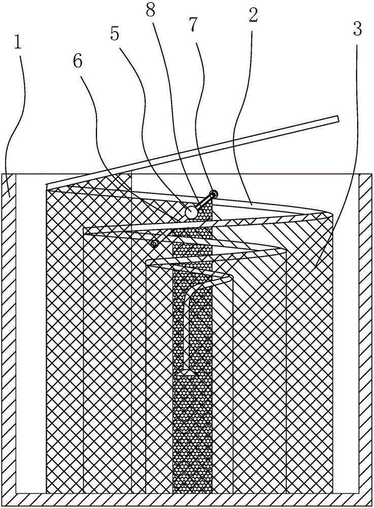
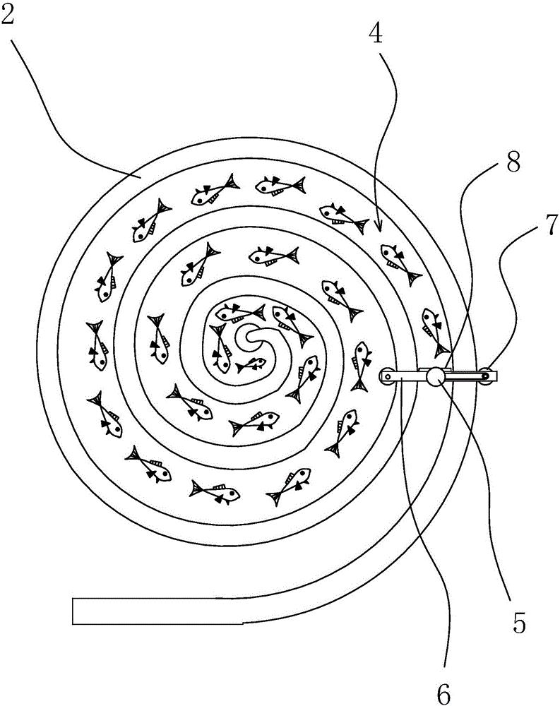
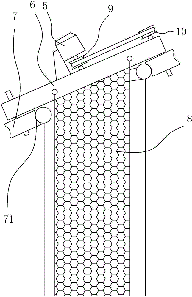
[0021] Such as Figure 1-3 Shown, this fish-suction pump uses the fish-suction pipe device, comprises the fish-suction pipe body 2 that can stretch into net cage 1, motor 5, connecting rod 6 and two guide wheels 7 that are connected to connecting rod 6 two ends in rotation respectively. The fish suction pipe body 2 is in a spiral shape, and the fish suction pipe body 2 is hung with a curtain body 3 along the spiral direction, and a spiral channel 4 is formed between the curtain bodies 3, and the connecting rod 6 is located above the spiral channel 4, so that The connecting rod 6 is hung with a net-shaped stop body 8, the stop body 8 is located in the spiral channel 4, and the two guide wheels 7 are respectively against the side walls of the fish suction pipe body 2 on both sides of the spiral channel 4, The motor 5 is arranged on the connecting rod 6, and the motor 5 is covered with a waterproof sealing shell, and the motor 5 and the guide wheel 7 are connected by a transmissi...

Embodiment 2

[0026] The structure of this embodiment is basically the same as that of Embodiment 1, except that the transmission mechanism includes a driving gear connected to the rotating shaft of the motor 5 and a driven gear connected to one of the guide wheels 7, the driving gear and the driven gear Mesh. The rotating shaft of motor 5 rotates and then drives the driving gear to rotate, and the driven gear meshed with it rotates accordingly, and the guide wheel 7 connected to the driven gear rotates coaxially thereupon, thereby being able to roll along the fish suction pipe body 2, and then drive Another guide wheel 7 can also roll along the fish suction pipe body 2, so that the baffle body 8 moves forward, and the fish is driven to the fish suction mouth of the fish suction pipe body located at the center of the net cage 1, thereby improving the efficiency of fish suction .


PUM


Abstract

The invention provides a fish sucking pipe device used for a fish sucking pump and belongs to the mechanical technical field. The fish sucking pipe device used for fish sucking pump comprises a fish sucking pipe body; the fish sucking pipe body is spiral shaped; curtain bodies are installed on the fish sucking pipe body in a hanging mode in a spiral direction and a spiral channel is formed among the curtain bodies; the fish sucking pipe device also comprises a motor, a connecting rod and two guiding wheels which are rotationally connected to two ends of the connecting rod; a netted blocking body is installed on the connecting rod in a hanging mode; the blocking body is positioned inside the spiral channel; the two guiding wheels are abutted on side walls of the fish sucking pipe body at two sides of the spiral channel; the motor is installed on the connecting rod; the motor and the guiding wheels are connected through a transmission mechanism which can drive the guiding wheels to roll along the fish sucking pipe body. According to the fish sucking pipe device used for a fish sucking pump, curtain bodies and a netted blocking body are installed on the spiral fish sucking pipe; the guiding wheels can be driven by the motor to roll along the spiral fish sucking pipe body so that the blocking body move forwards to drive fish to a port at a center position of the fish sucking pipe, therefore the fish sucking efficiency is increased.

Description

technical field [0001] The invention belongs to the technical field of machinery and relates to a fish suction pipe device for a fish suction pump. Background technique [0002] At present, in aquaculture, especially in large-scale aquaculture ponds and large-scale deep-water cage base aquaculture, due to the increasing scale of aquaculture, the output of farmed fish is also increasing. Currently, a single large-scale deep-water cage can be aquaculture 10 to 50 tons of finished live fish, so when the fish is raised large, the live fish must be caught and sold in a timely manner to ensure the economic benefits of farming, but such a large number of finished live fish must be caught and maintain a high survival rate. Because there is no suitable fast and efficient mechanized fishing equipment, fishing is a big problem. At present, only artificial fishing or crane-type equipment is used to fish with hanging baskets. The speed is slow for a long time, and the mechanical damage ...

Claims


Application Information

Patent Timeline
IPC IPC(8): A01K79/00
CPCA01K79/00
Inventor 张玉莲王伟
Owner ZHEJIANG OCEAN UNIV
Learn More