Self-suction centrifugal pump with high cavitation resistance

A centrifugal pump and cavitation technology, which is applied to pumps, parts of pumping devices for elastic fluids, and drive pumps, can solve problems such as weakening inlet backflow, and achieve weakening secondary flow vortices, reducing cavitation and Low-frequency pressure pulsation, easy to disassemble and replace

Active Publication Date: 2016-12-07
ZHEJIANG UNIV OF TECH
View PDF8 Cites 3 Cited by
  • Summary
  • Abstract
  • Description
  • Claims
  • Application Information

AI Technical Summary

Problems solved by technology

However, it has not been found to prevent or weaken the inlet backflow fundamentally through a certain structure to improve the anti-cavitation performance

Method used


Image

  • Self-suction centrifugal pump with high cavitation resistance
  • Self-suction centrifugal pump with high cavitation resistance
  • Self-suction centrifugal pump with high cavitation resistance

Examples


Embodiment 1

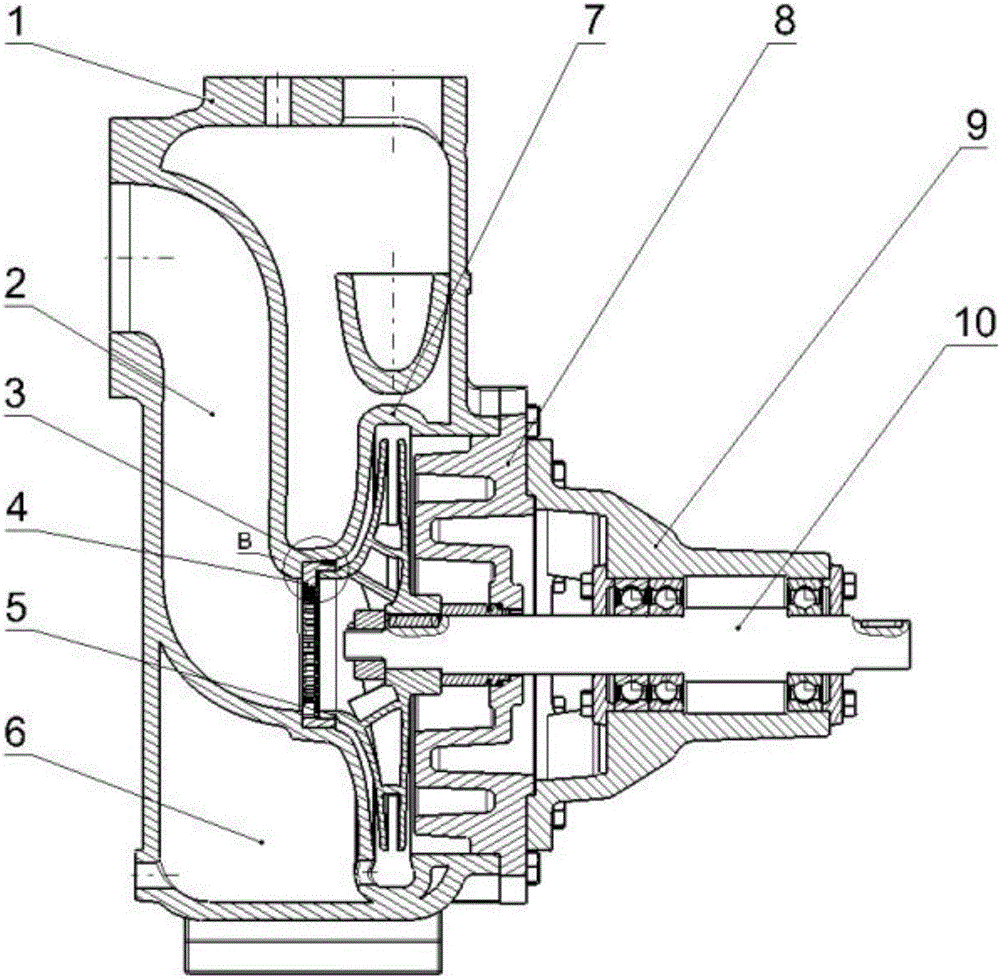
[0033] refer to Figure 1 to Figure 3b , a self-priming centrifugal pump with high cavitation resistance, including a pump body 1, a pump cover 8, a bearing frame 9 and an impeller 5 mounted on a pump shaft 10, a bearing is provided on the bearing frame 9, and a pump shaft 10 is arranged inside the bearing, There is a pump cover 8 on one side of the bearing frame 9; there are three cavities on the pump body 1, which are respectively the water absorption chamber 2, the liquid storage chamber 6 and the pressure water chamber 7, the liquid storage chamber 6 and the water absorption chamber 2, and the pressure water chamber 7 In communication, a rectification ring 4 is installed at the outlet of the water absorption chamber 2, and the rectification ring 4 includes a zigzag annular baffle 41 on the front side that can suppress the backflow of the axial surface inlet and secondary flow in the section and a rear side Ring sleeve 42; the inner circumference of the front side of the re...

Embodiment 2

[0044] This embodiment proposes a self-priming centrifugal pump with high cavitation resistance, wherein the seam-riding screw 3 is made of stainless steel to prevent it from being disassembled due to erosion or corrosion.

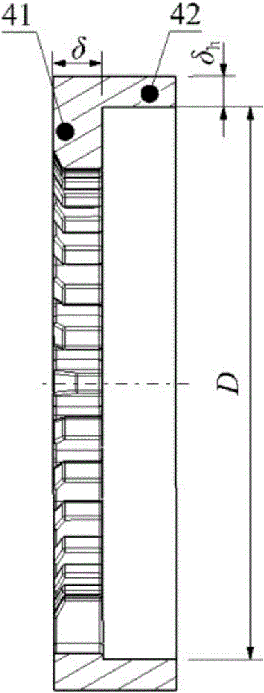
[0045] Such as Figure 3a with 3b Shown, impeller inlet diameter D 0 = 80mm, the axial thickness of the sawtooth baffle δ = 8mm, the thickness of the ring sleeve δ h = 5mm. This embodiment selects k=1 / 16, that is, the sawtooth height h=1 / 16D 0 , the lengthened tooth height is 2 times h, that is, 2h=1 / 8D 0 , the circumferential width of the sawtooth and the gap correspond to the central angle θ=ω=6°. The gap between the two sides of the sawtooth at the top of the sawtooth encryption area is the smallest ω 1 =1°, and then gradually transition to the non-encrypted area, and the transition gap is ω 2 =1.5°, ω 3 =2.5°, ω 4 =3.5°, ω 5 = 4.5° and ω 6 =5°, thus finally determine the number of sawtooth n=33, and the structure of the entire rectifying rin...


PUM


Abstract

Provided is a self-suction centrifugal pump with high cavitation resistance. The self-suction centrifugal pump with high cavitation resistance comprises a pump body, a pump cover, a bearing frame and an impeller installed on a pump shaft. The pump body is provided with three cavities, namely the water suction chamber, the liquid storage chamber and the water pressing chamber. The liquid storage chamber communicates with the water suction chamber and the water pressing chamber. A rectifying ring is installed at an outlet of the water suction chamber and comprises a sawtooth type annular baffle on the front side and a ring sleeve on the rear side. The sawtooth type annular baffle can restrain backflow of an axial plane inlet and secondary flow of a section. A plurality of grooves are formed in the inner circumference of the front side of the rectifying ring at intervals, and the multiple grooves define the circle of sawtooth type annular baffle. The interval between sawteeth on the upper side of the sawtooth type annular baffle is small, and the sawteeth with the small intervals form a sawtooth dense area. The size of the sawteeth on the left side and the right side of the sawtooth type annular baffle is increased. The inner circle of the ring sleeve is matched with an impeller opening ring, and the axial dimension of the ring sleeve is coincident with the impeller opening ring. The outer circle of the ring sleeve is fixedly matched with the pump body, the front side of the ring sleeve is flush with the outlet end face of the water suction chamber, and the rear side of the ring sleeve is flush with a convex plate on the pump body. The self-suction centrifugal pump can weaken inlet backflow and prewhirl to the greatest extent.

Description

technical field [0001] The invention relates to a self-priming centrifugal pump with high cavitation resistance, belonging to the technical field of self-priming centrifugal pumps. Background technique [0002] The phenomenon of cavitation caused by inlet backflow in centrifugal pumps is ubiquitous, especially in small flow conditions. The fluid particles rotating at the inlet of the impeller move radially outward under the action of centrifugal force, and are hindered by the front cover plate at the outer edge. Into the impeller, thus forming a backflow. The backflow fluid has a circumferential rotation speed consistent with the rotation direction of the impeller. After the backflow mixes with the main flow, it transfers the energy of rotation to the main flow, causing the main flow to generate pre-swirl and generate a low-pressure area at the center of rotation, thereby promoting cavitation. [0003] Because of its good self-priming performance and working stability, sel...

Claims


Application Information

Patent Timeline
Patent Type & Authority Applications(China)
IPC IPC(8): F04D9/02F04D29/00F04D29/66F04D29/62
CPCF04D9/02F04D29/007F04D29/628F04D29/669
Inventor 周佩剑吴振兴牟介刚简捷郑水华谷云庆吴登昊
Owner ZHEJIANG UNIV OF TECH
Why Eureka
Try Eureka