
A compartment type relief valve and its working method

A relief valve, compartment technology, used in safety valves, valve operation/release devices, valve details, etc., can solve problems such as low tank pressure and main valve opening

Active Publication Date: 2018-07-06
SHANGHAI AEROSPACE SYST ENG INST
View PDF6 Cites 0 Cited by
  • Summary
  • Abstract
  • Description
  • Claims
  • Application Information

AI Technical Summary

Problems solved by technology

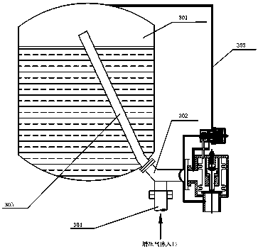
[0006] In order to solve the above-mentioned deficiencies in the prior art, the present invention provides a cavity-separated safety relief valve, which separates the command valve control cavity from the feedback cavity, the control cavity draws pressure from the storage tank, and the feedback cavity from the main valve port (gas inlet ) pressure introduction to solve the problem of low tank pressure and the early opening of the main valve caused by the existing safety relief valve under the current installation method

Method used


Image

  • A compartment type relief valve and its working method
  • A compartment type relief valve and its working method
  • A compartment type relief valve and its working method

Examples


Embodiment Construction

[0029] Now in conjunction with embodiment, accompanying drawing, the present invention will be further described:

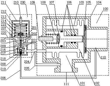
[0030] Such as figure 2 As shown, a compartment type relief valve in the embodiment of the present invention includes a main valve 100 and a command valve 200, the main valve 100 includes a main valve chamber 101 and a back pressure chamber 102, the main valve chamber 101 and a back pressure chamber 102 are separated by a bellows assembly 103, the command valve 200 includes a control chamber 201 and a feedback chamber 202, the control chamber 201 and the feedback chamber 202 are separated by a bellows 203, the feedback chamber 202 and the deflation chamber 221 They are connected or disconnected through the live valve 217, the deflation chamber 221 is connected with the back pressure chamber 102 through the communication pipe 204, the feedback chamber 202 is connected with the main valve chamber 101 through the drainage pipe 205, the command valve gas outlet 219 ...


PUM


Abstract

A separation cavity type relief valve comprises a main valve body and a check valve body, wherein the main valve body comprises a main valve cavity and a backpressure cavity which are separated by a corrugated pipe combination piece; the check valve body comprises a control valve, a feedback cavity and a deflation cavity; the control cavity and the feedback cavity are separated by a corrugated pipe; the feedback cavity and the deflation cavity are connected or disconnected through a movable valve; the deflation cavity is connected with the backpressure cavity through a communication pipe; the feedback cavity is connected with the main valve cavity through a drainage pipe; and a gas outlet of the check valve body is connected with a gas outlet of the main valve body through a vent pipe. The control cavity and the feedback cavity of the check valve body are separated, the control cavity draws pressure from a storage tank, the feedback cavity draws pressure from a main valve port, and therefore the problems that in an existing installation mode of an existing relief valve, the pressure of a storage tank is too low and a main valve is opened in advance are solved.

Description

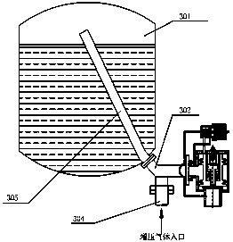
technical field [0001] The invention relates to a relief valve and a working method, in particular to a chamber-separated relief valve and a working method used in launch vehicles in active service. Background technique [0002] The relief valve is an important single unit used in the pressurized delivery system of the launch vehicle. Its function is to protect the pressure of the tank from exceeding the set value; when the propellant in the tank needs to overflow, it can be forced to open the overflow propellant. [0003] The installation method of the relief valve in the pressurized delivery system of the active launch vehicle is as follows: figure 1 As shown, it includes: tank air pillow, tee, safety overflow valve, booster pipe for the outer section of the tank and booster tube for the inner section of the tank. The pressurization pipe in the inner section of the tank installed obliquely in the tank communicates with the air pillow of the tank, and the other end is conn...

Claims


Application Information

Patent Timeline
Patent Type & Authority Patents(China)
IPC IPC(8): F16K17/10F16K31/126
CPCF16K17/044F16K17/10F16K31/126
Inventor 陈其法王文彬赵永立郭志海臧辉刘红宝石玉鹏
Owner SHANGHAI AEROSPACE SYST ENG INST
Learn More