An electric meter automatic closing device
A technology of automatic closing and ammeter, which is applied to the contact drive mechanism and the power device inside the switch, etc., can solve the problems of wasting manpower and troublesome operation, and achieve the effect of reducing manual closing and realizing integrated operation
- Summary
- Abstract
- Description
- Claims
- Application Information
AI Technical Summary
Problems solved by technology
Method used
Image
Examples
Embodiment 1
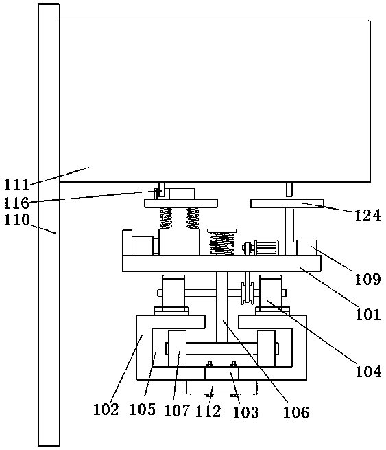
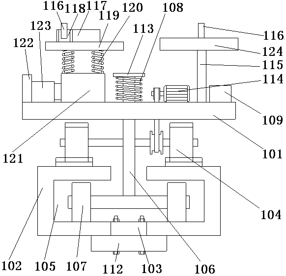
[0020] Such as figure 1 , 2 . As shown in 3, an electric meter automatic closing device includes a box body 110 and an electric meter 111 arranged parallel to the inside of the box body 110, and an electric meter 111 parallel to the electric meter 111 is arranged inside the box body 110. The bracket 112 is provided with a base 101 above the bracket 112, and two rails 102 are arranged between the base 101 and the bracket 112. The rails 102 are in a U-shaped structure, and the two rails The U-shaped openings of the above-mentioned rails 102 are arranged facing each other, and the middle parts of the two rails 102 are provided with mounting plates 103 arranged at intervals, and the mounting plates 103 are fixedly connected to the brackets 112 by bolts. Two sets of gears 104 are arranged below the base 101, two positioning grooves 105 are formed inside the two rails 102, and a driving motor 114 is arranged above the base 101, and the driving motor 114 is used to drive The gear 1...
Embodiment 2
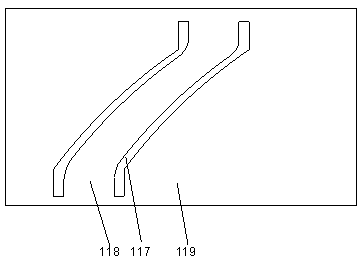
[0024] In this embodiment, for the convenience of installation, preferably, a support frame 119 is provided above the base 101 , and the two side plates 117 are located on the support frame 119 . After the two side plates are installed on the support frame, when the switch is located inside the slideway, the bottom of the switch will not touch the upper end surface of the support frame, so as to avoid the switch from colliding with the support frame when entering the slideway and causing the switch to break or fall off.
[0025] Further preferably, in order to prevent the switch from breaking due to contact with the bottom of the support frame, in this embodiment, a compression spring 120 is provided between the support frame 119 and the base 101 . In this embodiment, the two ends of the support frame close to the input end and the output end of the slideway are curved downward. When the switch enters the slideway, even if it encounters an ammeter with a long switch length, th...
Embodiment 3
[0027]In this embodiment, multiple groups of switches with the same model are installed in a row, so that when the switches are turned on or off at the same time, the positions of the switches are the same. The base 101 is provided with a sliding support 121, a baffle 122 is provided on the side wall of the base 101, a hydraulic cylinder 123 is provided on the baffle 122, and the hydraulic cylinder 123 The bottom is fixedly connected to the baffle plate 122, the telescopic rod of the hydraulic cylinder 123 is fixedly connected to the sliding support 121, and the bottom of the compression spring 120 is fixedly connected to the sliding support 121. Above, the hydraulic cylinder 123 is connected with the controller 109 through a line.
[0028] When needed, the hydraulic cylinder can be driven by the controller, so that the hydraulic cylinder pushes the sliding support to move, so that it is suitable for opening and closing switches of different electric meters.
[0029] In order...
PUM
 Abstract
Description
Claims
Application Information
 - R&D
- Intellectual Property
- Life Sciences
- Materials
- Tech Scout
- Unparalleled Data Quality
- Higher Quality Content
- 60% Fewer Hallucinations
Browse by: Latest US Patents, China's latest patents, Technical Efficacy Thesaurus, Application Domain, Technology Topic, Popular Technical Reports.
© 2025 PatSnap. All rights reserved.Legal|Privacy policy|Modern Slavery Act Transparency Statement|Sitemap|About US| Contact US: help@patsnap.com


