Cable wire erecting device for electric power repairing

A technology for emergency repair of electric power and cable racks, applied in the direction of overhead lines/cable equipment, etc., can solve the problems of inability to obtain safety guarantee, danger of emergency repair personnel, and high labor intensity, so as to avoid dumping, improve overhead efficiency, and extend the effect of laying distance.

Active Publication Date: 2016-12-07
HANGZHOU CCRFID MICROELECTRONICS
View PDF14 Cites 1 Cited by
  • Summary
  • Abstract
  • Description
  • Claims
  • Application Information

AI Technical Summary

Problems solved by technology

Although a large number of electric emergency repair vehicles are currently used, when encountering natural disasters, they are often accompanied by objective restrictions such as road congestion and serious damage to the roads. As a result, electric emergency repair vehicles cannot reach the accident scene quickly and in time, and can only rely on manual rescue on foot. Especially in mountainous areas, this often leads to long operation time, low efficiency, high labor intensity, and there is a great danger to the repair personnel, and safety cannot be guaranteed

Method used


Image

  • Cable wire erecting device for electric power repairing
  • Cable wire erecting device for electric power repairing
  • Cable wire erecting device for electric power repairing

Examples


Embodiment Construction

[0047] Below in conjunction with the accompanying drawings, the present invention will be described in detail through specific embodiments, but the use and purpose of these exemplary embodiments are only used to illustrate the present invention, and do not constitute any form of any limitation on the actual protection scope of the present invention, let alone The protection scope of the present invention is limited thereto.

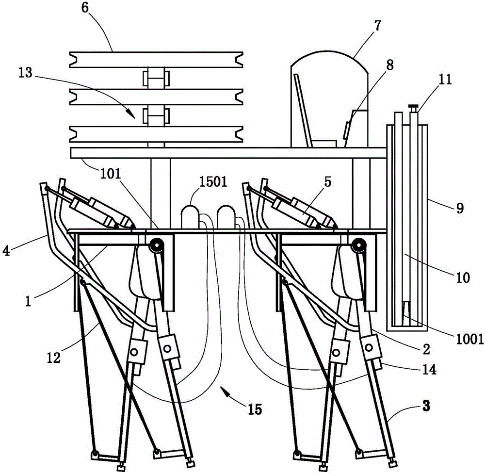
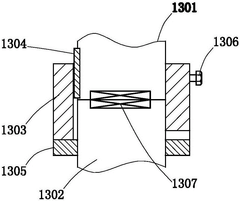
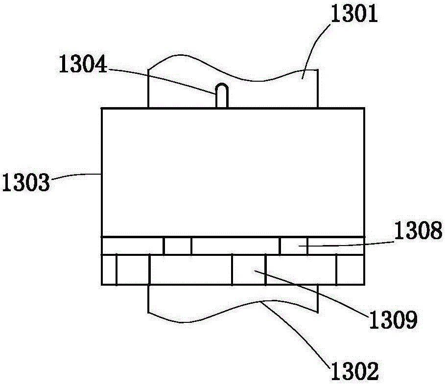
[0048] like figure 1 , figure 2 and image 3 Commonly shown, the present invention discloses a cable stringing device for emergency repair of electric power. The cable stringing device includes a frame 1, and the frame 1 is provided with a horizontally arranged console 101. The front and rear sides of the console 101 are Both ends are hingedly equipped with two opposite upper swing arms 2, and each upper swing arm 2 is hingedly equipped with a lower swing arm, and each upper swing arm 2 is connected with a driving arm 4, and the driving arm 4 is connec...


PUM


Abstract

The invention discloses a cable wire erecting device for electric power repairing. The cable wire erecting device comprises a rack. The rack is provided with an operating platform. The operating platform is provided with two upper swing arms, each upper swing arm is provided with a lower swing arm and connected with a drive arm, the drive arms are connected with a drive oil cylinder, a cylinder block of the drive oil cylinder is installed on the operating platform, and a piston rod of the drive oil cylinder is installed on the drive arms. The operating platform is provided with a cable wire spool. The rack is provided with a storage box. The storage box is internally provided with a cable supporting rod. The cable supporting rod comprises an installation segment and a cable supporting segment. A triangular fork is installed at one end of the installation segment, and an internal thread is arranged at the other end of the installation segment. An external thread is arranged at one end of the cable supporting segment, a supporting cross beam is arranged at the other end of the cable supporting segment, a cable rotatable disk is installed at one end of the supporting cross beam, and a cable fixing clip is arranged at the other end of the supporting cross beam. By means of the specific structural design, the cable wire erecting device has a plurality of advantages, can be applied to constructions such as electric power repairing and cable wire erecting and has good application prospects and industrial production potential.

Description

technical field [0001] The invention relates to the technical field of electric power maintenance devices, in particular to a cable stringing device for emergency repair of electric power. Background technique [0002] In modern industrialized society, people's life, work, and business operations are closely related to electricity all the time. Once a power failure occurs, it will bring great inconvenience to people's life and the normal operation of society. Especially when natural disasters such as storms, snowstorms, and earthquakes (such as the large-scale power interruption caused by the large-scale freezing on the eve of the Spring Festival in my country in 2009) will destroy the power supply, which will not only endanger people's normal life and industrial production, but also affect rescue work. It caused great inconvenience and delayed the rescue time. [0003] How to quickly repair the damaged power supply lines after encountering natural disasters has always been ...

Claims


Application Information

Patent Timeline
Patent Type & Authority Applications(China)
IPC IPC(8): H02G1/02
CPCH02G1/02
Inventor 不公告发明人
Owner HANGZHOU CCRFID MICROELECTRONICS
Why Eureka
Try Eureka