Eureka AIR delivers breakthrough ideas for toughest innovation challenges, trusted by R&D personnel around the world.

Control method for full-power power range shifting of hydro-mechanical stepless transmission

A stepless transmission, hydraulic machinery technology, applied in mechanical equipment, transmission devices, fluid transmission devices, etc., can solve the problems of sudden change in the speed of fixed displacement hydraulic components, power interruption, output speed fluctuations, etc., to eliminate speed fluctuations and power Interruption, reduce slippage, improve the effect of changing section quality

Active Publication Date: 2016-12-21
YANSHAN UNIV
View PDF6 Cites 2 Cited by
  • Summary
  • Abstract
  • Description
  • Claims
  • Application Information

AI Technical Summary

Problems solved by technology

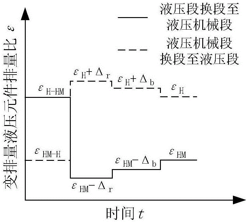
During the section change, the load of the hydraulic transmission mechanism is reversed, the power flow of the hydraulic circuit is reversed, the functions of the hydraulic components are interchanged, and the high and low pressure sides of the hydraulic circuit are interchanged, resulting in a sudden change in the speed of the constant displacement hydraulic components, causing fluctuations in the output speed, and causing power interruption

Method used


Image

  • Control method for full-power power range shifting of hydro-mechanical stepless transmission
  • Control method for full-power power range shifting of hydro-mechanical stepless transmission
  • Control method for full-power power range shifting of hydro-mechanical stepless transmission

Examples


Embodiment Construction

[0030] The core of the present invention is to provide a hydraulic machinery stepless transmission full power power shifting control method, which enables the hydraulic machinery to complete the smooth transition from the current segment to the target segment in the combination and overlap of the two clutches, realizes power transfer, and is in the shifting process. During the segment process, the power can be transmitted normally, and the full-power power shifting can be realized.

[0031] In order to make those skilled in the art better understand the technical solutions of the present invention, the present invention will be further described in detail below with reference to the accompanying drawings and specific embodiments.

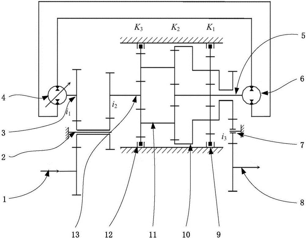
[0032] In this embodiment, the figure 2 A certain differential two-stage hydromechanical stepless transmission shown implements full power power shift control. The transmission device can be divided into two working conditions: hydraulic section a...


PUM


Abstract

The invention provides a control method for full-power power range shifting of hydro-mechanical stepless transmission. The control method comprises the following steps: a hydro-mechanical controller monitors key state parameters such as the rotating speed, the pressure and the like of the current range in real time; a ratio of the rotating speed of a constant-displacement hydraulic component to an input rotating speed is taken as a criterion of ideal timing for range shifting; a clutch in a target range engages at the ideal range shifting timing, hydraulic machinery enters a previous stable range from the current range; the controller predicts the working state of the target range according to the key state parameters of the current range and plans a displacement regulation process in a power transition process; pressure release and pressure building processes on high-pressure and low-pressure sides of a closed hydraulic circuit are controlled actively by regulating the displacement of the constant-displacement hydraulic component according to the planned displacement regulation process in a power transition range, and power transition is realized; after completion of power transition, range shifting enters a later stable range; finally, a clutch in the current range disengages, range shifting is completed, and the hydraulic machinery enters the target range. With adoption of the range shifting control method, range shifting of the hydraulic machinery is completed in combination and overlapping of the two clutches, and stable transition from the current range to the target range is realized; power can be transmitted normally during range shifting, and full-power power range shifting is realized.

Description

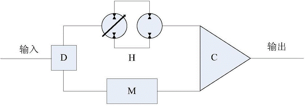
technical field [0001] The invention relates to the technical field of hydraulic machinery stepless transmission, in particular to a hydraulic machinery stepless transmission full-power power shifting control method. technical background [0002] Hydraulic mechanical stepless transmission is a transmission form composed of mechanical transmission and hydraulic transmission, such as figure 1 As shown in the figure, it consists of four parts: a power split mechanism D, a mechanical transmission mechanism M, a hydraulic transmission mechanism H, and a power confluence mechanism C. This transmission method has the outstanding advantages of high efficiency of mechanical transmission and stepless transmission of hydraulic transmission, and is suitable for high-power vehicles. [0003] The hydraulic-mechanical stepless transmission section change process is a transitional process in which two adjacent sections are alternated. During the transition, the load of the hydraulic trans...

Claims


Application Information

Patent Timeline
IPC IPC(8): F16H47/04
CPCF16H47/04
Inventor 杨树军鲍永杨得青范程远赵坤金诗峻
Owner YANSHAN UNIV
Why Eureka
Eureka Blog
Learn More