
control loop

A technology of control rings and fasteners, applied in the field of control gauges, can solve the problems of expensive purchase and maintenance, fragile, bulky, etc., and achieve the effect of reducing the risk of wrong positioning and simple equipment

Active Publication Date: 2020-09-25
LISI 航空
View PDF6 Cites 0 Cited by
  • Summary
  • Abstract
  • Description
  • Claims
  • Application Information

AI Technical Summary

Problems solved by technology

[0008] These units are reliable, but expensive to purchase and maintain, bulky, fragile, and require specially trained staff

Method used


Image

  • control loop
  • control loop
  • control loop

Examples


Embodiment Construction

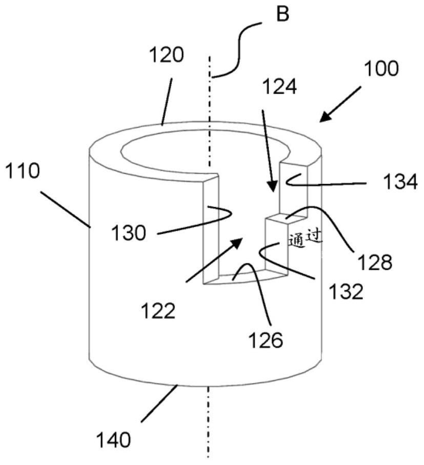
[0053] figure 2 A first embodiment of a control loop 100 according to the invention is shown. The control ring 100 comprises a tubular body 110 with an axis of rotation B, which is equipped with a through-hole which emerges at a first extreme end 120 of said tubular body and at a second extreme end 140 opposite the first extreme. The ring is made of aluminum, for example. The inner diameter of the ring is matched within a tolerance to the outer diameter of the shaft 14 of the fastener to be inspected so that the ring can slide on the shaft 14 without excessive resistance.

[0054] The first end 120 of the body includes two U-shaped notches 122 and 124 that extend axially from the end 120 through a portion of the body 110 to end walls 126 and 128 , respectively. The end walls 126 and 128 extend in parallel planes perpendicular to the axis B and are axially offset from each other. The two notches 122 and 124 are adjacent and have different axial lengths and widths (or arcuat...


PUM


Abstract

A control ring and a method of using a control ring on fasteners can be used to verify a headed fastener having a band coating a fastener shaft. The ring comprises a cylindrical tubular body extending along an axis of revolution (B) and two opposite extremities. A first extremity includes two adjacent arc segments, each arc segment having an end wall extending in a plane perpendicular to the axis of revolution (B) of the ring, the planes of the two walls not being one and the same and axially offset from the first extremity. Each arc segment comprises at least one side wall extending over a radial plane going through the axis of revolution (B) of the ring. The width of an arc segment allows verifying a minimum band width, and the width of the two arc segments allows verifying a maximum band width on the fastener.

Description

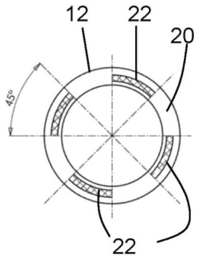
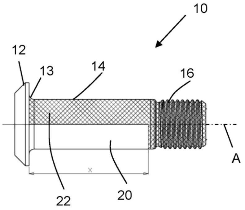
technical field [0001] The present invention relates to a control gauge designed to verify that the dimensional characteristics of a fastener conform to the design of the fastener as it leaves the manufacturing line. More precisely, the present invention relates to a control ring for fasteners of the type comprising an enlarged head and a cylindrical shaft extending along an axis comprising at least one coated layer belt. Such a fastener is described in application FR 3 008 754 and in Figure 1A and Figure 1B shown in the table. This type of fastener is used to assemble metallic and composite structures in aircraft. Background technique [0002] Figure 1A and Figure 1B A metal fastener 10 of the type described above is shown in end and side views, respectively, and includes a projecting head 12, a cylindrical shaft 14, and a threaded portion 16. In variations, the fastener may include a pull rod that may pull the fastener for interference insertion into the pre-drill...

Claims


Application Information

Patent Timeline
Patent Type & Authority Patents(China)
IPC IPC(8): G01B5/02
CPCG01B3/26G01B5/02G01B3/34G01B3/36
Inventor 亚历山大·贝尔图马夏尔·布鲁克克里斯托弗·帕亚得
Owner LISI 航空
Learn More