Dynamic power flow control device based on wide range controllable transformer with bidirectional power transistor

A technology for controlling device and dynamic power flow, applied in the direction of AC network with different sources of the same frequency, etc., can solve problems such as large loss, mutual influence of FACTS device controllers, and difficulty in popularization and application.

Active Publication Date: 2019-11-19
上海驹电电气科技有限公司
View PDF2 Cites 0 Cited by
  • Summary
  • Abstract
  • Description
  • Claims
  • Application Information

AI Technical Summary

Problems solved by technology

However, due to the complexity of power system control, the current FACTS technology also has great limitations:
[0007] (1) FACTS device controllers interact with each other, leading to performance deterioration;
[0008] (2) The cost of the project is high, and it is difficult to popularize and apply;
[0009] (3) The loss of itself is relatively large;
[0010] (4) Power system stability problems caused by FACTS device failure
[0011] Invention patent CN 102801160 B proposes a dynamic power flow controller based on voltage amplitude and phase angle control and its control method. Although it can solve some problems, its phase angle adjustment range can only lead and not lag, so it can only adjust the system in one direction Trend, no two-way adjustment capability

Method used


Image

  • Dynamic power flow control device based on wide range controllable transformer with bidirectional power transistor
  • Dynamic power flow control device based on wide range controllable transformer with bidirectional power transistor
  • Dynamic power flow control device based on wide range controllable transformer with bidirectional power transistor

Examples


Embodiment Construction

[0086] The present invention will be further described below in conjunction with the embodiments and accompanying drawings, but the protection scope of the present invention should not be limited thereby.

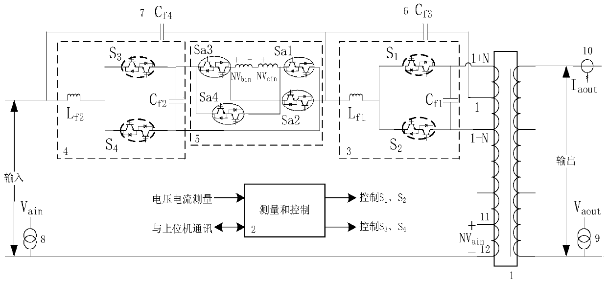
[0087] see first figure 1 , figure 1 It is a structural schematic diagram of a dynamic power flow control device based on a wide-range controllable transformer including a bidirectional power tube of the present invention. It can be seen from the figure that a dynamic power flow control device based on a wide-range controllable transformer with a bidirectional power tube is characterized in that the device includes: a wide-range controllable transformer 1, a measurement and control module 2, a first power unit 3, a second Second power unit 4, cross-phase conversion module 5, third filter capacitor 6, fourth filter capacitor 7, input voltage transformer 8, output voltage transformer 9 and output current transformer 10:

[0088] The primary side of the wide-range controllab...


PUM


Abstract

The invention discloses a dynamic tide flow control device based on a wide-range controllable transformer comprising bidirectional power tubes, and the device consists of a controllable transformer, a power unit, a measurement and control module, a cross phase conversion module, a filter capacitor, an input / output voltage transformer, and an output current transformer. The control method of a dynamic tide flow comprises the steps: controlling the on / off of a tapping point at an input side (a primary side) of the wide-range controllable transformer through employing a power electronic switch which can achieve quick switching-on and switching-off; connecting another two windings at a tapping point of each phase of the wide-range controllable transformer in a series manner; adding four groups of bidirectional power tubes too change the switching-on direction of the cross phase conversion module, thereby changing the phase and amplitude of the output voltage of the controllable transformer in the largest range, and achieving the adjustment of active power and reactive power. The method carries out the control of the switching-on of the tapping point of the wide-range controllable transformer, thereby achieving the regulation and control of the dynamic tide flow of a power grid. The device is low in cost, and is high in control reliability of the dynamic tide flow.

Description

technical field [0001] The invention relates to the technical field of flexible AC power transmission, in particular to a dynamic power flow control device and a control method based on a wide range controllable transformer including a bidirectional power tube. Background technique [0002] With the interconnection of large-scale power systems and the use of various new equipment, while making power generation and transmission more economical and efficient, the scale and complexity of the power system have also increased, and the possibility of the power grid operating on the edge of the stability limit has also greatly increased. . At present, my country has reached a new stage of regional power grid interconnection and national unified networking. Large-scale interconnection brings many advantages, but grid operation and stability control will become more complex. The flexibility of grid operation, controllability of power flow and grid stability have become more and mor...

Claims


Application Information

Patent Timeline
Patent Type & Authority Patents(China)
IPC IPC(8): H02J3/06
CPCH02J3/06
Inventor 冯琳江秀臣汪可友韩蓓李国杰王琨
Owner 上海驹电电气科技有限公司
Why Eureka
Try Eureka