A power amplifier circuit

A technology of power amplification circuit and circuit, which is applied in the direction of amplifiers, push-pull amplifiers, amplifiers with semiconductor devices/discharge tubes, etc., and can solve the problems of small voltage signals being easily interfered, no good solution, poor load capacity, etc.

Active Publication Date: 2018-08-03
BEIJING CED RAILWAY ELECTRIC TECH
View PDF3 Cites 0 Cited by
  • Summary
  • Abstract
  • Description
  • Claims
  • Application Information

AI Technical Summary

Problems solved by technology

The voltage signal output by most sensors is AC5V, and the load capacity is poor
Small voltage signals are easily disturbed in the complex electromagnetic environment of the EMU, and cannot provide accurate information to the locomotive control unit
[0003] For the above situation, the prior art does not have a good solution

Method used


Image

  • A power amplifier circuit
  • A power amplifier circuit
  • A power amplifier circuit

Examples


Embodiment Construction

[0037] The technical solutions in the embodiments of the present invention will be clearly and completely described below in conjunction with the accompanying drawings in the embodiments of the present invention. Obviously, the described embodiments are only some of the embodiments of the present invention, not all of them. Based on the embodiments of the present invention, all other embodiments obtained by persons of ordinary skill in the art without making creative efforts belong to the protection scope of the present invention.

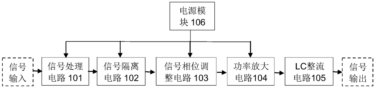
[0038] figure 1 A schematic structural diagram of a power amplifier circuit provided by an embodiment of the present invention. Such as figure 1 As shown, it mainly includes: a signal processing circuit 101 , a signal isolation circuit 102 , a signal phase adjustment circuit 103 , a power amplifier circuit 104 and an inductor-capacitor LC rectifier circuit 105 connected in sequence.

[0039] At the same time, the circuit also includes a power sup...


PUM


Abstract

The invention discloses a power amplifying circuit; the circuit comprises a signal processing circuit, a signal isolating circuit, a signal phase position adjusting circuit, the power amplifying circuit and an inductance-capacitance LC rectifying circuit, wherein the signal processing circuit, the signal isolating circuit, the signal phase position adjusting circuit, the power amplifying circuit and the inductance-capacitance LC rectifying circuit are successively connected. By adopting the circuit disclosed by the invention, through adjusting resistance of resistors of the signal processing circuit, the output of an isolation transformer of the signal isolating circuit can be changed; by adjusting the resistance of the resistors of the signal phase position adjusting circuit, the phase position of an output signal is changed; and thus, the load capacity is improved, and the requirement of long-distance transmission of voltage information is met.

Description

technical field [0001] The invention relates to the field of integrated circuit design, in particular to a power amplifier circuit. Background technique [0002] During the operation of the EMU, the train control unit needs to collect and monitor the information of the speed sensor, temperature sensor, current sensor and other sensors to ensure the safe operation of each equipment. The voltage signal output by most sensors is AC5V, and the load capacity is poor. Small voltage signals are easily disturbed in the complex electromagnetic environment of the EMU, and cannot provide accurate information to the locomotive control unit. [0003] For the above situation, the prior art does not have a good solution. Contents of the invention [0004] The purpose of the present invention is to provide a power amplifying circuit, which changes the size of the output voltage, improves the carrying capacity, and satisfies the requirement of long-distance transmission of voltage inform...

Claims


Application Information

Patent Timeline
Patent Type & Authority Patents(China)
IPC IPC(8): H03F3/217H03F3/26
CPCH03F3/217H03F3/26H03F2203/211
Inventor 高文斌杨建明刘志华苏安社王俊峰
Owner BEIJING CED RAILWAY ELECTRIC TECH
Why Eureka
Try Eureka