Gas sensor

a technology of gas sensor and sensor, applied in the field of gas sensor, can solve the problems of long-term drift of sensor output, difficult to determine whether a change in sensor output is a response, and difficult to determine whether a gas sensor is not responding, so as to eliminate the change in output, stabilize the reaction, and respond differently.

Active Publication Date: 2012-10-09
UNIV OKAYAMA
View PDF8 Cites 4 Cited by
  • Summary
  • Abstract
  • Description
  • Claims
  • Application Information

AI Technical Summary

Benefits of technology

[0017]With the gas sensor according to the embodiments of the present invention, the gate metal materials of the two field-effect transistors are different from one another, resulting in different response properties relative to hydrogen gas. The difference in response property can be utilized to measure target hydrogen gas. Response to gas is actually possible with a conventional gas sensor using a single field-effect transistor, in which a gate metal reacts with measurement target gas to change the work function of the gate metal. However, the conventional gas sensor using a single sensor component might undergo drift of sensor output due to change in properties of the field-effect transistor over time. On the contrary, the gas sensor according to the embodiments of the present invention uses two field-effect transistors having the same structures other than the gate metal materials. At the same time, the gate electrodes of the two field-effect transistors are coupled to one another by wiring, instead of being separated, so that the one voltage applying means applies a constant voltage to the gate electrodes. This ensures same operating conditions for the two field-effect transistors constituting the gas sensor. Thus, even though the gas sensor is used for a long term, the two field-effect transistors are used in the same environment. Further, since the two field-effect transistors have the same structures (sensor structures), similar changes in properties occur. Further, the two field-effect transistors commonly undergo disturbances such as electromagnetic noise and change in temperature. This ensures that the differential amplifier measures a difference between outputs of the two field-effect transistors and compensates for the differential, thereby eliminating change in output due to disturbances and change in properties.
[0018]The gas sensor according to the embodiments of the present invention includes a common ion conductive film on the gate electrodes of the two field-effect transistors so that when exposed to measurement target gas, the gate electrodes react with the gas through the ion conductive film. This stabilizes the reaction and improves gas selectivity.

Problems solved by technology

Many conventional gas sensors have met, through long use, the problem of varied sensor output, i.e., long-term drift of sensor output.
This makes it difficult to determine whether a change in sensor output is a response to gas or merely a result of drift.
It is also difficult to determine whether a gas sensor is not responding because of breakdown or because, simply, there is no gas to be sensed.

Method used


Image

  • Gas sensor
  • Gas sensor
  • Gas sensor

Examples


embodiment 1

[Embodiment 1]

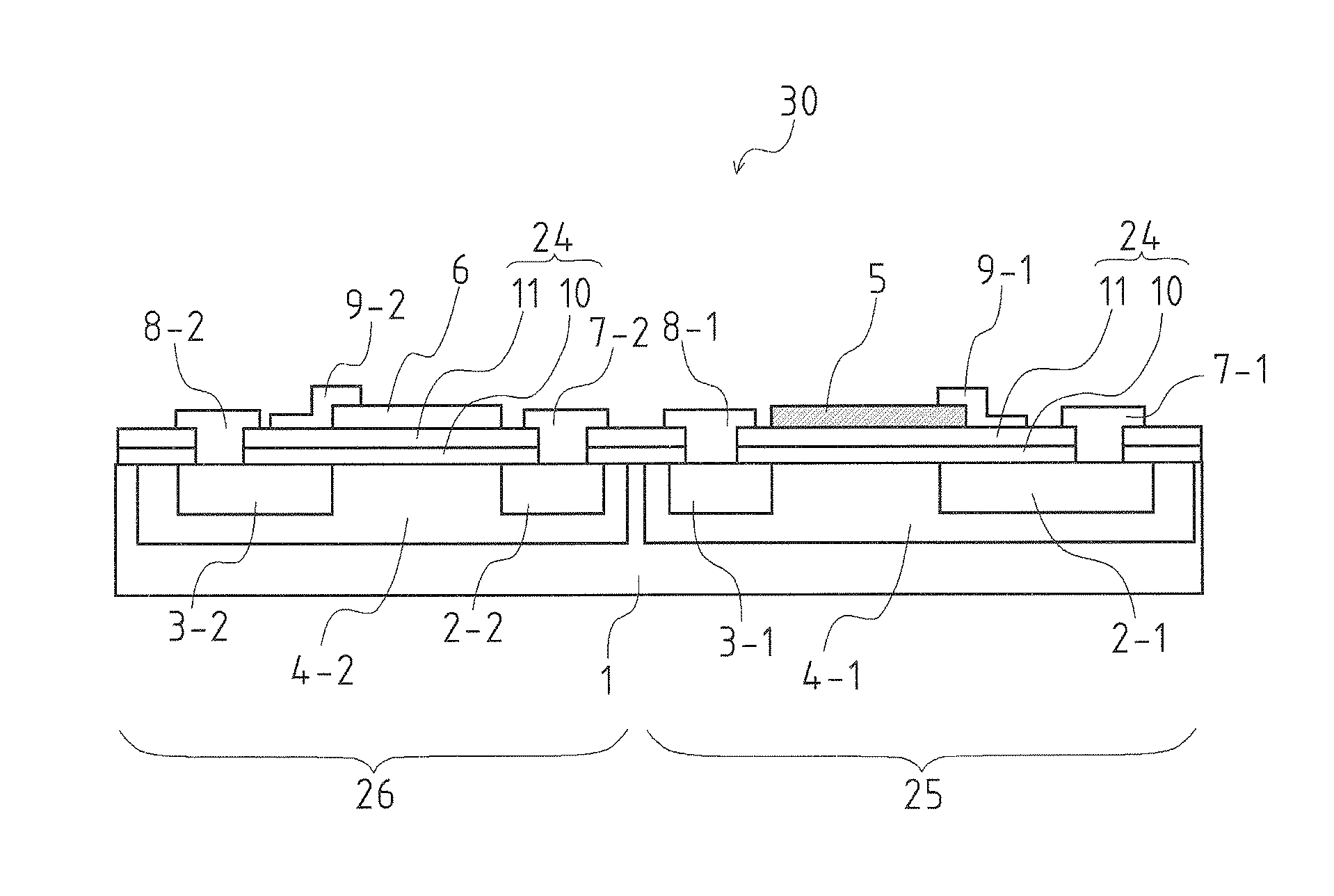
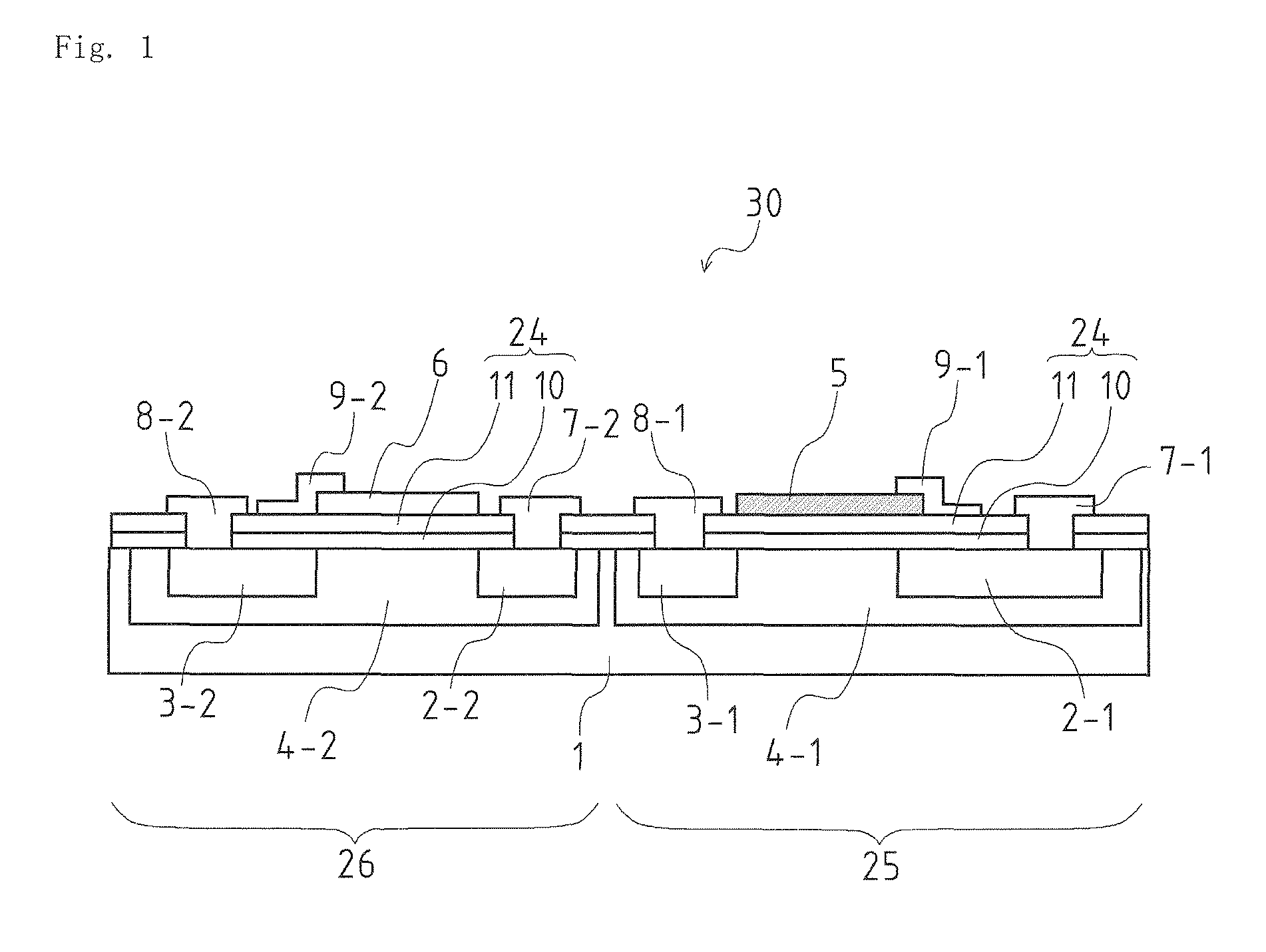
[0053]FIG. 1 is a schematic cross-sectional view of a gas sensor according to an embodiment of the present invention, illustrating a basic structure of the gas sensor including two field-effect transistors, A gas sensor 30 illustrated in FIG. 1 is a field-effect gas sensor in which two field-effect transistors using mutually different metal materials as gate electrodes are integrated on one Si substrate 1. That is, the gas sensor 30 includes two n-type channel field-effect transistors provided on the Si substrate 1.

[0054]A catalytic metal gate field-effect transistor 25 (hereinafter referred to as catalytic metal gate transistor), which is one of the two field-effect transistors, includes a Pt gate electrode 5 formed as a first gate electrode. Using Pt (platinum), which is an example of catalytic metal, as a gate electrode material of the first gate electrode, the catalytic metal gate transistor 25 functions as a gas sensor to respond to hydrogen. Hydrogen, when expose...

embodiment 2

[Embodiment 2]

[0064]FIG. 5 shows an alternating-current source 23 serving as voltage applying means added to the gas measuring circuit in FIG. 3. The alternating-current source 23 applies an alternating-current voltage ΔAC commonly to the two field-effect transistors, namely, the catalytic metal gate transistor 25 and the non-catalytic metal gate transistor 26. This signal, i.e., the alternating-current voltage ΔAC, and alternating-current components ΔAC1 and ΔAC2 of outputs of the two field-effect transistors have the relationship ΔAC1=ΔAC2=ΔAC during normal operation of the two field-effect transistors. Therefore, the alternating-current voltage signal does not exist in the output difference of the differential amplifier 21. However, if either of the two field-effect transistors breaks down, the broken field-effect transistor shows no alternating-current voltage signal in its output or shows a different level of alternating-current voltage signal to result in ΔAC1≠ΔAC2. The differ...

embodiment 3

[Embodiment 3]

[0070]FIG. 6 is a schematic view of the gas sensor 30 including the two field effect transistors according to an embodiment of the present invention, illustrating a basic structure of a sensor chip plane having a common ion conductive film formed on the gate electrodes. In order to couple the gas sensor 30 to an external measuring circuit (not shown), a drain electrode pad 27, a source electrode pad 28, and a gate wiring electrode pad 29 of the catalytic metal gate transistor 25, and a drain electrode pad 31, a source electrode pad 32, and a gate wiring electrode pad 33 of the non-catalytic metal gate transistor 26 are provided adjacent to the chip of the gas sensor 30. The Pt gate electrode 5 and the Ti gate electrode 6 is covered with a common ion conductive film 12. The common ion conductive film 12 in the present embodiment is a perfluoro-ion-exchange film having proton conductivity. The perfluoro-ion-exchange film having proton conductivity selectively allows prot...


PUM

PropertyMeasurementUnit
operating temperaturesaaaaaaaaaa
dissociation responseaaaaaaaaaa
direct-current voltageaaaaaaaaaa

Abstract

A gas sensor (30) includes two field-effect transistors and gate electrodes on gate insulation films (24) of the two field-effect transistors to detect gas using the gate electrodes. The gas sensor (30) includes a first gate electrode (5), a second gate electrode (6), and voltage applying means. The first gate electrode (5) is provided on one of the field-effect transistors. The second gate electrode (6) is provided on another one of the field-effect transistors. The voltage applying means is for, with the first gate electrode (5) and the second gate electrode (6) coupled to one another by wiring, applying thereto one of a direct-current voltage and an alternating-current voltage having a same potential or a constant voltage difference. The first gate electrode (5) and the second gate electrode (6) are made of different metals. The one field-effect transistor and the other field-effect transistor have approximately the same structures.

Description

TECHNICAL FIELD[0001]The present invention relates to a gas sensor to detect gas concentration.BACKGROUND ART[0002]A wide variety of gas sensors are known. For example, a metal oxidant (SnO2) having semiconductor properties varies its resistance value when exposed to hydrogen gas due to reduction of the oxygen in the metal oxidant. Some semiconductor hydrogen sensors utilize the change in resistance value to determine gas concentration. A similar principle is used in hot-wire semiconductor hydrogen sensors, in which a metal-oxide semiconductor is fused to a platinum wire also serving as a heater and a bridge circuit detects a change in resistance value of a device. These semiconductor and hot-wire gas sensors use bulk materials that are detrimental to mass productivity and that require operating temperatures of equal to or higher than about 300° C.[0003]Further, such electrochemical sensors are reported that have a solid electrolyte between a platinum electrode and a nickel electrod...

Claims


Application Information

Patent Timeline
Patent Type & Authority Patents(United States)
IPC IPC(8): G01N27/403
CPCG01N27/4148G01N27/4141
Inventor TSUKADA, KEIJI
Owner UNIV OKAYAMA
Why Eureka
Try Eureka