
Positioning and clamping tool for laser welding of stainless steel side wall

A laser welding, positioning and clamping technology, which is applied in laser welding equipment, welding equipment, welding equipment, etc., can solve the problem that the laser welding scheme cannot be implemented, affects the streamline and aesthetics of the curved surface, and the outer wall of the side wall is compressed and deformed, etc. question

Active Publication Date: 2017-01-25
CRRC CHANGCHUN RAILWAY VEHICLES CO LTD
View PDF4 Cites 13 Cited by
  • Summary
  • Abstract
  • Description
  • Claims
  • Application Information

AI Technical Summary

Problems solved by technology

[0005] In order to solve the problem that the conventional welding and positioning method for large thick-walled plates using multiple quick clamps cannot be applied to the laser welding scheme of the stainless steel side wall of the rail vehicle, the crimping point of the quick clamps is likely to cause failure of the outer side wall of the side wall. The compression deformation of the recovery affects the streamlined and aesthetics of its curved surface; and the distance between the lower end surface of the corrugated plate and the inner wall of the side wall due to the inability to implement precise fastening of a large area located in the middle of the side wall The value often exceeds the gap control requirements stipulated by the laser welding process, which leads to the technical problem that the laser welding scheme cannot be implemented. The invention provides a positioning and clamping tool for laser welding stainless steel side walls

Method used


Image

  • Positioning and clamping tool for laser welding of stainless steel side wall
  • Positioning and clamping tool for laser welding of stainless steel side wall
  • Positioning and clamping tool for laser welding of stainless steel side wall

Examples


Embodiment Construction

[0022] The present invention will be described in further detail below in conjunction with the accompanying drawings.

[0023] Such as Figure 4 to Figure 9 As shown, the positioning and clamping tooling for laser welding stainless steel side walls of the present invention includes a table top 3 and a base 4. The shape of the table top 3 is the same as that of the curved surface profile of the side wall body 1, and the overall profile of the upper end surface of the base 4 is the same as that of the table top 3. The overall profile of the lower end surface matches, and the table top 3 is fixedly connected to the base 4 by bolts. The table top 3 is provided with a plurality of ventilation slots, and each ventilation slot is provided with at least one air extraction hole, and the table top 3 is provided with grooves around the positions corresponding to the openings on the side wall 1, and the grooves are filled with sealing rubber strips .

[0024] The table top 3 includes an...


PUM


Abstract

The invention provides a positioning and clamping tool for laser welding of a stainless steel side wall and belongs to the field of an auxiliary side wall positioning device used in a laser welding technology for the stainless steel side wall of a railway vehicle. The tool comprises a table board and a base, wherein the shape of the table board is the same as that of a curve profile of the outer side wall of a side wall body, the overall profile of the upper end surface of the base is matched with that of the lower end surface of the table board, and the table board is fixedly connected onto the base through bolts; multiple vent grooves are formed in the table board, at least one air extraction hole is formed in each vent groove, grooves are formed in the periphery of the position, corresponding to the holes in the side wall body, of the table board, and the grooves are filled with seal rubber strips. According to the tool, a value of a gap between the lower end surface of a corrugated plate and an inner side wall of the side wall body can be controlled in a predetermined spacing range more easily and is enabled to totally meet the high-standard control requirement of the laser welding technology for a reserved weld gap value, and finally, the laser welding technology is enabled to be applied to the welding field of the stainless steel side wall of the railway vehicle.

Description

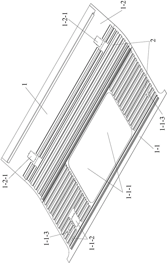
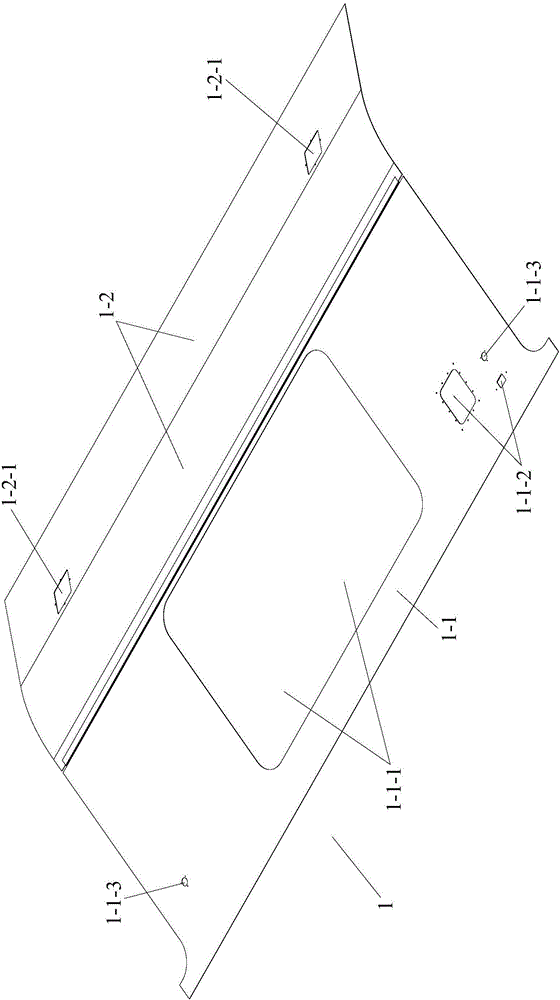
technical field [0001] The invention belongs to the field of side wall auxiliary positioning devices used in the process of laser welding stainless steel side walls of rail vehicles, and in particular relates to a positioning and clamping tool for laser welding stainless steel side walls. Background technique [0002] Such as Figure 1 to Figure 3 As shown, the stainless steel side wall of the rail vehicle is formed by welding a plurality of corrugated plates 2 in parallel on the inner side wall of the side wall body 1. The wallboard 1-1 and the lower wallboard 1-2 are butt welded. The upper wall plate 1-1 is a flat thin plate, and its end face is provided with a window area 1-1-1, two small square holes 1-1-2 on the upper wall plate and two small round holes 1-1-3 on the upper wall plate . The main body of the lower wallboard 1-2 is an arc-shaped plate, and two small square holes 1-2-1 of the lower wallboard are provided on its end face. Both sides of the lower end surfa...

Claims


Application Information

Patent Timeline
IPC IPC(8): B23K26/70B23K37/04
CPCB23K26/702B23K37/0443
Inventor 夏常青赵国新秦晓哲
Owner CRRC CHANGCHUN RAILWAY VEHICLES CO LTD
Learn More