Shooting training device easy to replace shooting target and smooth in operation

A training device and shooting target technology, which is applied in the field of shooting targets, can solve the problems of time-consuming and laborious replacement of shooting targets, holes that cannot be eliminated, etc.

Inactive Publication Date: 2017-02-01
范爱苏
4 Cites 0 Cited by

AI-Extracted Technical Summary

Problems solved by technology

[0002] In shooting training, the shooting target is made of wood or foam. After multiple shots with darts or bullets, there are many holes on the cloth surface of the shooting target. These holes can not be eliminated, but will also become dee...

Method used

[0015] Due to the ability to store multiple groups of shooting targets, it is possible to meet the needs of selection and replacement in shooting training. Furthermore, the planarity of each shooting target is not affected and disturbed in the storage device. By providing the clamping portion that can protrude inward beyond the guide rib, it can drive the shooting target in both upward and downward directions without affecting the driving of the shooting target in the front and rear directions. By arranging the guide ribs...

Abstract

The invention relates to a shooting training device easy to replace a shooting target and smooth in operation. The shooting training device comprises a housing, wherein the inner space of the housing comprises a bottom storage area which is used for containing a plurality of shooting target assemblies, an upper front display area which is used for displaying a selected shooting target and an upper back shooting target sliding path area, a sliding driving assembly which extends in a forward and backward direction and is used for enabling the selected shooting target to slide in the forward and backward direction is arranged in the shooting target sliding path area, a floodlight device is arranged in the display area and is used for illuminating the display area at night or when natural light is dark, the floodlight device is an LED (Light Emitting Diode) floodlight, and each shooting target assembly comprises a shooting target mounting plate, lifting driving screws located on both sides of the shooting target mounting plate and a lifting support frame driven by the lifting driving screws.

Application Domain

Targets

Technology Topic

EngineeringFloodlight +3

Image

  • Shooting training device easy to replace shooting target and smooth in operation
  • Shooting training device easy to replace shooting target and smooth in operation
  • Shooting training device easy to replace shooting target and smooth in operation

Examples

  • Experimental program(1)

Example Embodiment

[0011] Combine below Figure 1-5 The present invention will be described in detail.
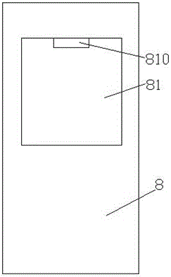
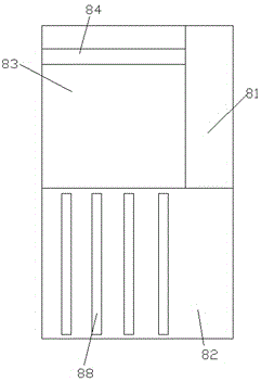
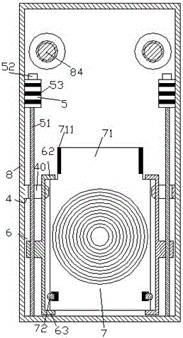
[0012] According to an embodiment of the present invention, a shooting training device that is easy to replace shooting targets and runs smoothly includes a housing 8, wherein the inner space of the housing 8 includes a bottom storage area 82 for accommodating a plurality of shooting target assemblies 88 , A display area 81 on the upper front side for displaying the selected shooting target and a shooting target sliding path area 83 on the upper back side. The shooting target sliding path area 83 is provided with a sliding drive assembly 84 extending in the forward and backward directions for To make the selected shooting target slide in the front and rear directions, the display area 81 is provided with a lighting device 810, and the lighting device 810 is used to illuminate the display area 81 at night or when the natural light is dark. The lighting device 810 is an LED lighting; wherein, each of the plurality of shooting target assemblies 88 includes a shooting target mounting plate 7 and a lifting drive screw 51 located on both sides of the shooting target mounting plate 7 and driven by the lifting The lifting support frame 6 is driven by a screw 51. The lifting driving screw 51 is driven by a driving motor 5 installed on the adjacent inner wall of the housing 8. The top of the driving motor 5 is provided with an electronic control device 52. The electronic control The device 52 is electrically connected to the driving motor 5, and the electronic control device 52 is used to control the rotation speed of the driving motor 5, so that the rotation speed of the driving motor 5 can be adjusted as needed to control the lifting support frame 6, Downward moving speed, the outer surface of the driving motor 5 is provided with a heat dissipation fin group 53 which is used to absorb and dissipate the heat generated during the operation of the driving motor 5 to prevent the driving motor 5 Burned out due to excessively high operating temperature for a long time; wherein, the inner side walls of the shell 8 located on both sides of the shooting target mounting plate 7 are respectively fixedly provided with guide ribs 4 extending forward and backward, and each guide rib 4 has A through hole 40 is provided for the lifting drive screw 51 and the main body of the lifting support frame 6 to pass through. The guide rib 4 is provided with an inclined sliding bearing portion at the end located outside the through hole 40. The upper and lower side surfaces of the inclined sliding bearing portion are respectively provided with an upper sliding inclined surface 41 and a lower pressing inclined surface 42. The upper sliding inclined surface 41 is used for elastically telescopic setting when the shooting target mounting plate 7 is in the upper position. The lower inclined surface 78 of the elastic telescopic pin 72 in the bottom side of the shooting target mounting plate 7 is slidably engaged, and the lower pressing inclined surface 42 is used when the shooting target mounting plate 7 is lifted from the down position. Engaged with the upper slope 79 of the elastic telescopic pin 72 to press and compress the elastic telescopic pin 72. The upper and lower sides of the elastic telescopic pin 72 close to the inside of the shooting target mounting plate 7 are provided with rollers 721, so The roller 721 is used to reduce the friction and wear caused by the elastic telescopic pin 72 when sliding, improve the flexibility of the elastic telescopic pin 72 and extend the service life; the upper and lower ends of the main body are respectively provided with extending in the inward direction The upper clamping protrusion 62 and the lower clamping protrusion 63 of the inclined sliding bearing portion beyond the guide rib 4 are used to clamp the shooting target mounting plate 7, and the shooting target mounting plate 7 is in contact with The upper clamping protrusion 62 is provided with a front and rear pushing connecting portion 71 on the joint portion. The left and right sides of the front and rear pushing connecting portion 71 are respectively provided with elastic joint surfaces 711 for the shooting target mounting plate 7 When the lifting drive screw 51 is lifted to the upper position state, it is respectively engaged with the screw drive rods 84 provided in the housing 8 and separated left and right, so as to realize the movement in the front and rear direction.
[0013] Advantageously, the guide rib 4 is always located between the upper clamping protrusion 62 and the lower clamping protrusion 63.
[0014] Beneficially or exemplarily, the inner side surface of the main body of the lifting support frame 6 is planarly matched with the inner side wall of the through hole 40 of the guide rib 4 so as to be guided in the up and down direction.
[0015] Since multiple sets of shooting targets can be stored, it can meet the selection and replacement needs in shooting training. Moreover, the planarity of each shooting target is not affected and disturbed in the storage device. By providing a clamping part that can extend inwardly beyond the guide ribs, it can target the shooting in both upward and downward directions for driving, and does not affect the driving of the shooting target in the front and rear directions. By arranging the guide rib, which cooperates with the telescopic support, the sliding support after lifting can be realized under the premise of allowing the shooting target to move up and down. By providing through holes in the guide ribs, it is possible to provide driving power transmission for the raising and lowering of the shooting target. The entire device can store multiple sets of shooting targets and is reliable in operation, and the cost is significantly lower than that of a liquid crystal device. It can well solve the problems in the prior art.
[0016] It is obvious to those skilled in the art that various modifications to the above embodiments can be made without departing from the overall spirit and concept of the present invention. All of them fall into the protection scope of the present invention. The protection scheme of the present invention is subject to the appended claims of the present invention.

PUM

no PUM

Description & Claims & Application Information

We can also present the details of the Description, Claims and Application information to help users get a comprehensive understanding of the technical details of the patent, such as background art, summary of invention, brief description of drawings, description of embodiments, and other original content. On the other hand, users can also determine the specific scope of protection of the technology through the list of claims; as well as understand the changes in the life cycle of the technology with the presentation of the patent timeline. Login to view more.
Why Eureka
Try Eureka