Injection molding method and injection molding die

一种注塑成形、模具的技术,应用在仪器、分析材料等方向,能够解决接合面变形平面性、局限成形件、贯通孔脱模阻力大等问题,达到脱模阻力减小、防止平面性的降低、脱模阻力小的效果

Inactive Publication Date: 2011-02-16
KONICA MINOLTA OPTO
View PDF2 Cites 1 Cited by
  • Summary
  • Abstract
  • Description
  • Claims
  • Application Information

AI Technical Summary

Problems solved by technology

[0015] However, in the above Figure 8 ~ Figure 10 In the method shown, since the through hole has a large release resistance, there is a problem that deformation of the joint surface occurs near the through hole and flatness decreases.
In addition, if Figure 11 The method shown, has the problem of being limited to a formed part where the entire surface of the substrate is empty

Method used


Image

  • Injection molding method and injection molding die
  • Injection molding method and injection molding die
  • Injection molding method and injection molding die

Examples


no. 1 approach

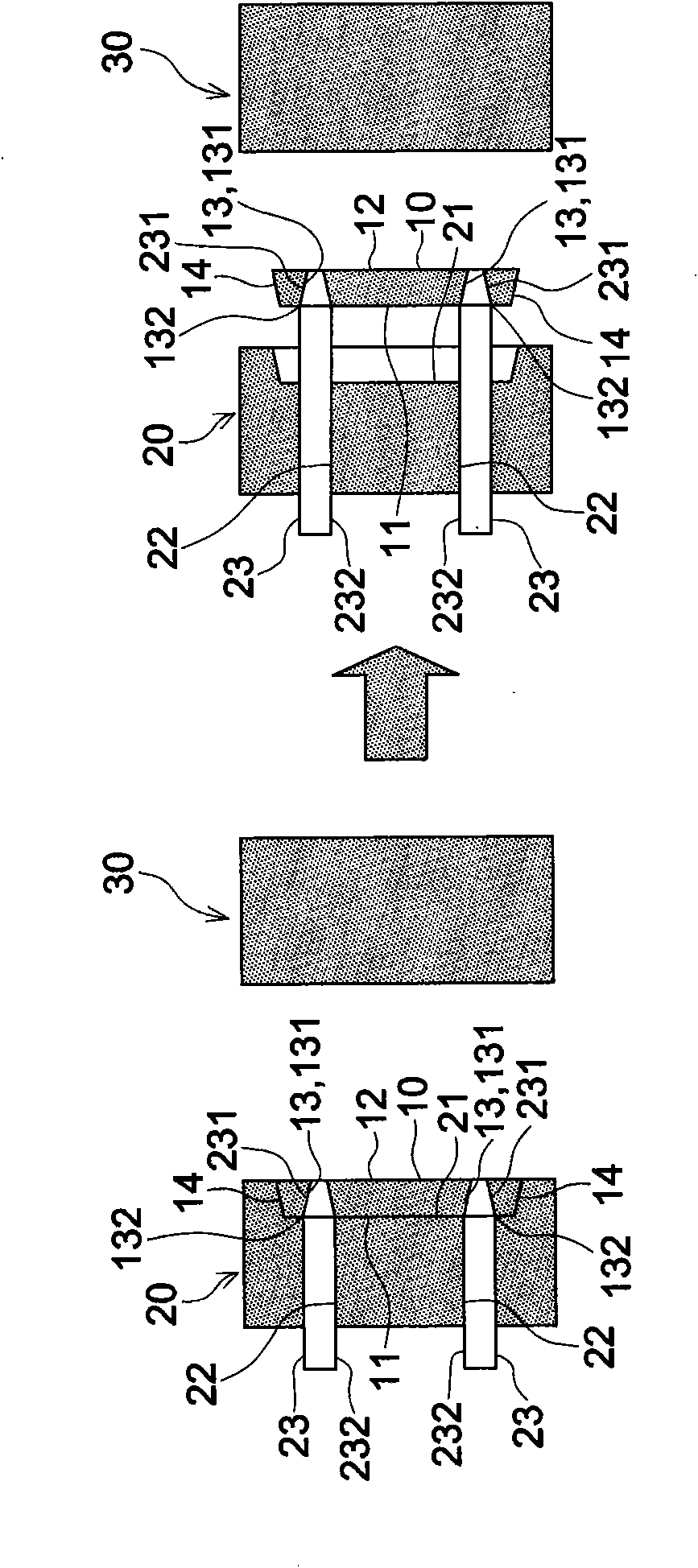
[0072] refer to figure 1 An injection molding die according to a first embodiment of the present invention will be described. figure 1 is a cross-sectional view of an injection molding die.

[0073] First, the plate-shaped substrate 10 molded using the injection molding die of the first embodiment will be described. The substrate 10 is provided with a through-hole 13 penetrating therethrough such that the diameter of the hole gradually decreases from one side surface 11 to the other side surface 12 . On the other side surface 12, a fine flow path (not shown) communicating with the through hole 13 is provided. A covering member (not shown) is bonded to the other side surface 12 on which the fine flow path 12 is provided. A microchip is constituted by the substrate 10 and a cover member bonded to the other side surface 12 of the substrate 10 . One side 11 of the substrate 10 is a flat surface without fine flow paths. In addition, the other side 12 on which the fine flow p...

no. 2 approach

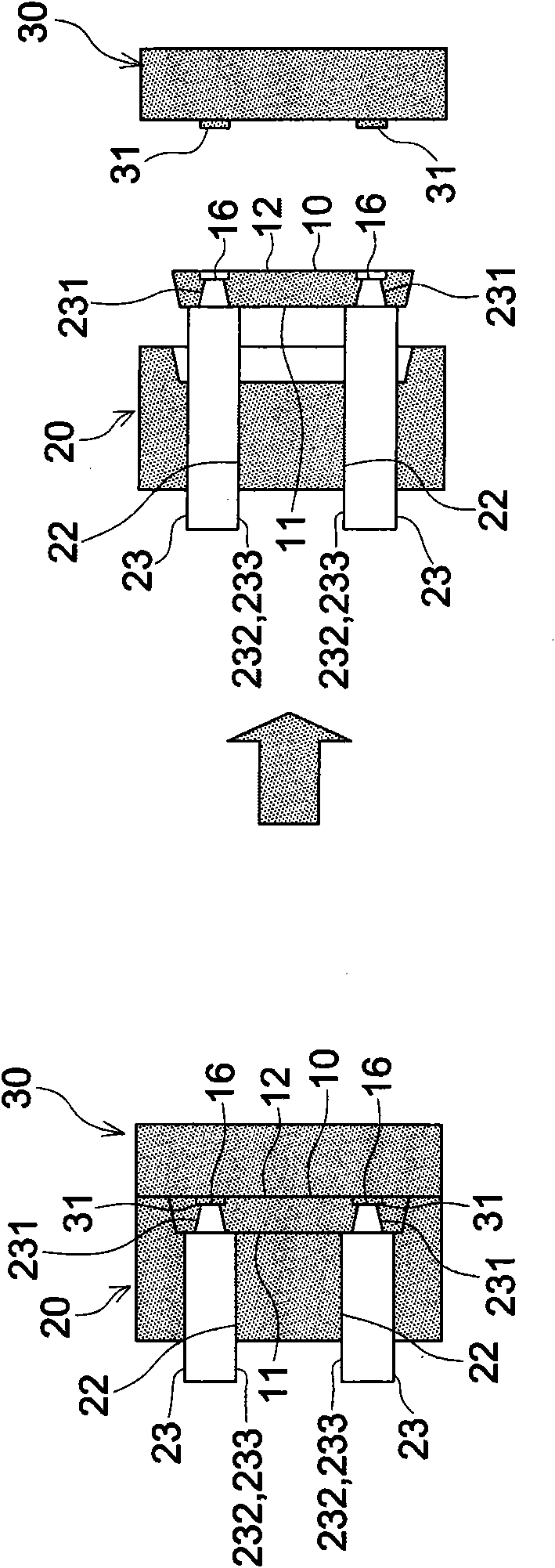
[0109] Below, refer to Figure 4 The injection molding die of the second embodiment will be described. Figure 4 It is a cross-sectional view of the injection molding die of the second embodiment.

[0110] First, the substrate 10 molded by the injection molding die of the second embodiment will be described. The board|substrate 10 of 2nd Embodiment differs from the board|substrate 10 of 1st Embodiment in that it has the cylindrical part (vent tube) 15. As shown in FIG.

[0111] The cylindrical portion 15 protrudes from one side 11 of the substrate 10 to the side opposite to the other side 12 . The other side 12 is a joint surface forming a fine flow path. Figure 4 (c) is a plan view showing the one-side mold 20 and the other side surface 12 (joint surface) of the substrate 10 with the other-side mold 30 opened.

[0112] The cylindrical portion 15 has a height that is three times or more the thickness of the substrate 10 . The height of the cylindrical portion 15 is gener...

no. 3 approach

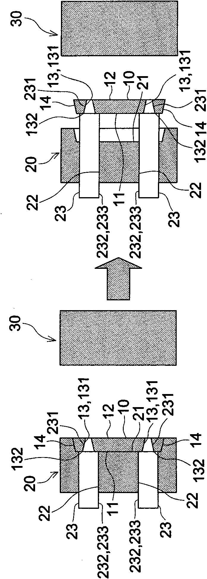
[0138] Below, refer to Figure 6 An injection molding die according to a third embodiment will be described. Figure 6 It is a cross-sectional view of the injection molding die of the third embodiment.

[0139] The injection molding die of the third embodiment is characterized in that the sleeve 24 of the second embodiment is not provided. In the third embodiment, the through hole 13 also penetrates through the center of the cylindrical portion 15 , and the mold release resistance of the through hole 13 is relatively large.

[0140] In the injection molding method of the third embodiment, there is included a pre-separation step of moving the tapered rod 23 toward the substrate 10, that is, the molded product, before the ejection step of the die 20 on the side where the molded product is separated by the tapered rod 23. The mold 30 on the other side sinks in the opposite direction, so that the inner wall 131 of the through hole 13 is separated from the tapered rod 23 .

[01...


PUM

PropertyMeasurementUnit
surface smoothnessaaaaaaaaaa
angleaaaaaaaaaa

Abstract

Provided is an injection molding method for a resin substrate, wherein: through-holes are provided on a plate-shaped substrate so that they are penetrated from one surface of the substrate in the direction of the other surface in a way such that the diameter of the hole gradually becomes smaller; and micro-passages that connect to the through-holes are provided on the other surface of the substrate. A cavity is formed by joining a first molding die that forms one surface with a second molding die that forms the other surface. One part of the first molding die that forms the through-holes comprises taper pins that protrude from the first molding die towards the second molding die. The substrate is formed by filling the cavity with resin material, and the substrate is released from the second molding die by separating the first molding die from the second molding die. By pushing out the inner walls of the through-holes with the taper pins that are projected further towards the second molding die, the substrate is released from the first molding die.

Description

technical field [0001] The present invention relates to an injection molding method and an injection molding die, and in particular to a method for injection molding a resin substrate having a fine flow path formed on at least one of both surfaces of a plate-like substrate and a cover member bonded to the surface on which the fine flow path is formed, and Injection molding mold. Background technique [0002] Using microfabrication technology to form microflow paths and circuits on silicon and glass substrates, micro analysis chips or micro analysis chips called μTAS (Micro Total Analysis Systems) has been put into practical use. An advantage of such a microchip is that it is possible to reduce the amount of samples and reagents used and the amount of waste liquid to be discharged, and to realize an inexpensive system that is portable due to space saving. A microchip is manufactured by bonding two members in which at least one member is microfabricated. [0003] Convention...

Claims


Application Information

Patent Timeline
Patent Type & Authority Applications(China)
IPC IPC(8): G01N37/00B29C45/40B29C45/37
CPCB29C45/40B29C45/2628
Inventor 关原干司
Owner KONICA MINOLTA OPTO
Why Eureka
Try Eureka