Planar microneedle, microneedle patch, manufacturing equipment, vertical equipment and preparation method

A technology for manufacturing equipment and microneedles, applied in the field of microneedles, can solve the problems of uncontrollable dosage, difficult demoulding, large depth of forming groove and depth-to-length ratio, etc., to avoid fracture, reduce demolding resistance, improve The effect of yield

Pending Publication Date: 2022-07-15
YOUWE ZHUHAI BIOTECH CO LTD
View PDF6 Cites 0 Cited by
  • Summary
  • Abstract
  • Description
  • Claims
  • Application Information

AI Technical Summary

Problems solved by technology

[0007] In view of the above-mentioned shortcomings and deficiencies of the prior art, the present invention provides a planar microneedle, microneedle stickers and manufacturing equipment, vertical equipment and preparation methods, which solve the problem of the depth of the forming groove of the mold in the existing microneedle manufacturing equipment. and the depth-to-length ratio are large, so that the tip, middle and base of the formed microneedle are all loaded with medicine, resulting in the inability to control the precise dosage, polluting the forming groove and affecting the technical problems of other batches of microneedles, and the forming groove The depth and depth-to-length ratio are both large, resulting in technical problems that are difficult to demould

Method used


Image

  • Planar microneedle, microneedle patch, manufacturing equipment, vertical equipment and preparation method
  • Planar microneedle, microneedle patch, manufacturing equipment, vertical equipment and preparation method
  • Planar microneedle, microneedle patch, manufacturing equipment, vertical equipment and preparation method

Examples


Embodiment 1

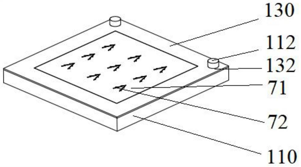
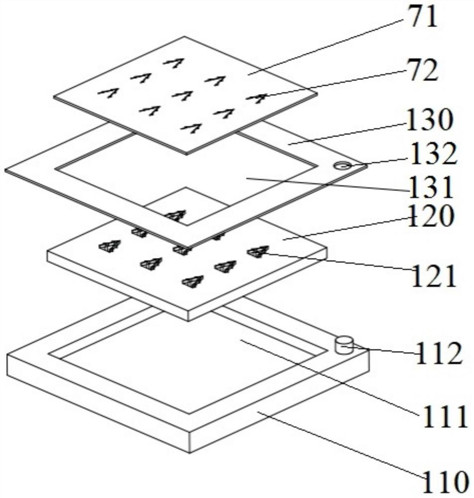
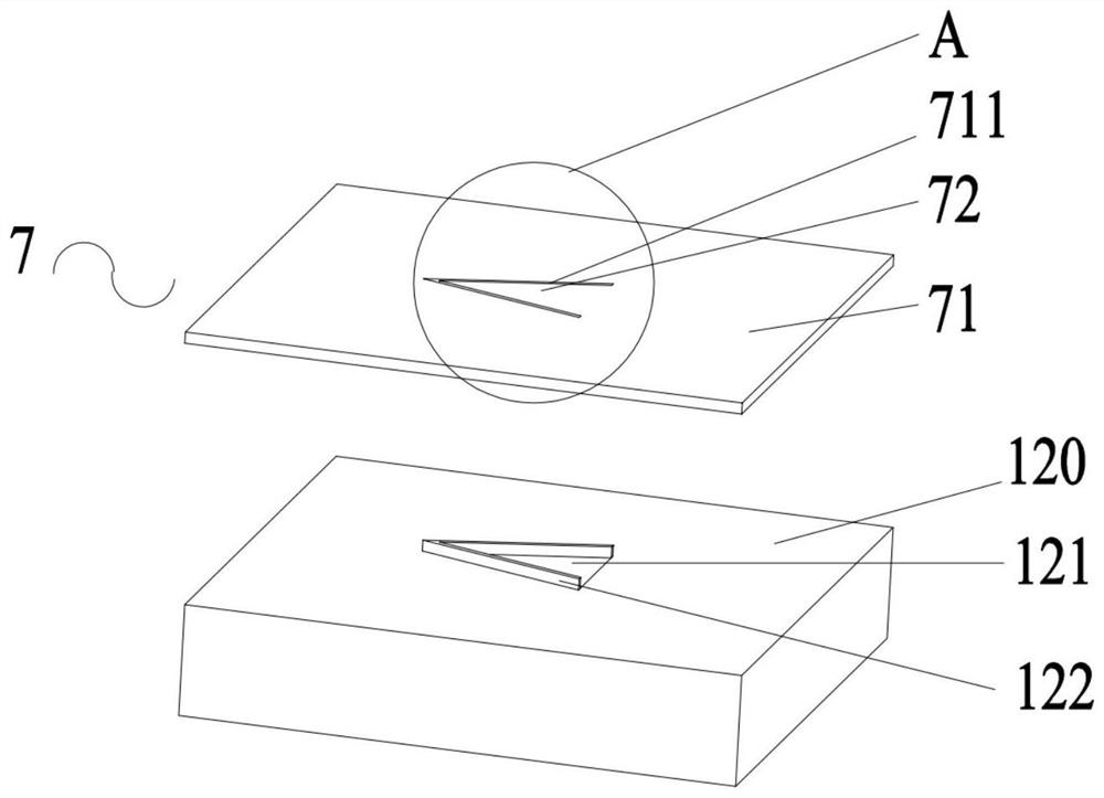
[0092] see Figure 1-32 As shown, an embodiment of the present invention provides a flat microneedle, including a base layer 71 and a microneedle 72 disposed on the base layer 71 . The microneedle 72 includes a needle tip 721 , a needle base 723 and a middle portion 722 connecting the needle tip 721 and the needle base 723 . The direction of the needle tip 721 toward the needle seat 723 is the same as the extending direction of the base layer 71 , and the microneedle 72 is formed by the forming groove 121 in the mold 120 . The direction of the needle tip groove 1211 for forming the needle tip 721 toward the needle seat groove 1213 for forming the needle seat 723 is horizontal, so as to reduce the depth of the forming groove 121 and reduce the ratio of the maximum depth to the maximum length of the forming groove 121 , so that the drug-carrying liquid can be accurately poured into the needle tip groove 1211 of the forming groove 121 . Since the forming groove 121 of the micro...

Embodiment 2

[0105] On the basis of Embodiment 1, this embodiment provides a microneedle patch 8 .

[0106] see Figure 1-32 , the microneedle patch 8 includes an adhesive layer 6 . The working principle of changing from the plane microneedle 7 to the microneedle sticker 8 is as follows: the adhesive layer 6 is adhered to the base layer 71 close to the side of the microneedle 72 protruding from the base layer 71 , the connection between the first surface 724 and the second surface 725 There is a gap 711 between the surface and the base layer 71, the microneedles 72 rotate around the connection between the third surface 726 and the base layer 71 until the third surface 726 and the base layer 71 are on the same plane, the microneedles 72 are vertical, and the third surface 726 is adhered to the adhesive layer 6, and the microneedles 72, the base layer 71 and the adhesive layer 6 are arranged in order from top to bottom and combined into the microneedle sticker 8. At this time, the direction...

Embodiment 3

[0110] see Figure 1-23 As shown, on the basis of Embodiment 1 and Embodiment 2, the embodiment of the present invention provides a manufacturing apparatus for flat microneedles.

[0111] The manufacturing equipment of the planar microneedle includes a base 110 , a mold 120 and a panel 130 located above the base 110 . The top of the base 110 is provided with an accommodating groove 111 for accommodating the mold 120 . The top of the mold 120 is provided with a plurality of molding grooves 121 for molding the microneedles 72 . The forming groove 121 includes a needle point groove 1211 , a needle seat groove 1213 and a middle groove 1212 connecting the needle point groove 1211 and the needle seat groove 1213 . The direction of the needle point groove 1211 toward the needle seat groove 1213 is a horizontal direction. The needle tip groove 1211 is used to form the needle tip 721 of the microneedle 72, the middle groove 1212 is used to form the middle part 722 of the microneedle ...


PUM


Abstract

The invention relates to a planar microneedle which comprises a substrate layer and a microneedle body arranged on the substrate layer in a turnover mode, the microneedle body comprises a needle tip, a needle base and a middle part connecting the needle tip and the needle base, and the direction, facing the needle base, of the needle tip is the same as the extending direction of the substrate layer. The invention also relates to manufacturing equipment of the planar microneedle, a preparation method of the planar microneedle, a microneedle patch and vertical equipment of the microneedle patch. The micro-needle has the beneficial effects that the direction of the needle point groove towards the needle seat groove is the horizontal direction, so that the depth of the forming groove and the ratio of the maximum depth to the maximum length of the forming groove are reduced, medicine carrying liquid is conveniently and accurately poured into the needle point groove of the forming groove, the situation that the medicine carrying liquid splashes to pollute the middle groove and the needle seat groove is avoided, and the formed micro-needle only carries medicine at the needle point.

Description

technical field [0001] The invention relates to the technical field of microneedles, in particular to a plane microneedle, a microneedle sticker and manufacturing equipment, a vertical equipment and a preparation method. Background technique [0002] At present, in drug injection, metal injection needles are generally used for operation. The pain and fear caused by the use of metal injection needles are difficult for some people (especially children) to accept. Therefore, microneedle patches have begun to be applied. [0003] The microneedle patch mainly includes a base layer and microneedles arranged on the base layer. When in use, the side of the microneedle with the microneedle is pressed and attached to the skin. Since the needle length of the microneedle is short, it will not cause nerve damage and pain during use, which is gradually recognized by the public. [0004] The microneedle sticker is mainly formed by a mold, and the drug-carrying liquid is poured into the m...

Claims


Application Information

Patent Timeline
Patent Type & Authority Applications(China)
IPC IPC(8): A61M37/00
CPCA61M37/0015A61M2037/0023A61M2037/0046A61M2037/0053
Inventor 李成国冷钢马永浩陈锦永陈莲华李燕芬
Owner YOUWE ZHUHAI BIOTECH CO LTD
Why Eureka
Try Eureka