Supercharge Your Innovation With Domain-Expert AI Agents!

Copper bar dehumidifying device and copper bar manufacturing method

A technology of copper rod and moving direction, which is applied in the direction of drying solid materials, drying gas arrangement, drying solid materials, etc. by combining methods, and can solve the problem of incomplete dehumidification of copper rods, etc.

Active Publication Date: 2017-02-15
富通昭和线缆(天津)有限公司 +2
View PDF4 Cites 2 Cited by
  • Summary
  • Abstract
  • Description
  • Claims
  • Application Information

AI Technical Summary

Problems solved by technology

[0005] The invention provides a copper rod dehumidification device and a copper rod manufacturing method to at least solve the problem of incomplete dehumidification of copper rods in the related art

Method used


Image

  • Copper bar dehumidifying device and copper bar manufacturing method

Examples


Embodiment Construction

[0018] Embodiments of a copper rod dehumidification device and a copper rod manufacturing method according to the present invention will be described below with reference to the accompanying drawings. Those skilled in the art would recognize that the described embodiments can be modified in various ways or combinations thereof without departing from the spirit and scope of the invention. Accordingly, the drawings and description are illustrative in nature and not intended to limit the scope of the claims. Also, in this specification, the drawings are not drawn to scale, and like reference numerals denote like parts.

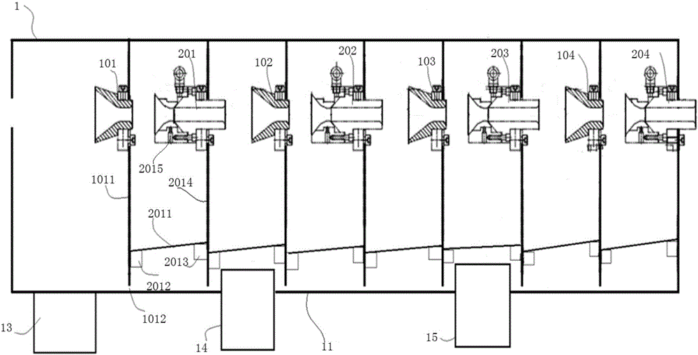
[0019] Such as figure 1 As shown, the copper rod dehumidification device of the present invention is a box-type structure, and the box body 1 is arranged horizontally along the moving direction of the copper rod. The two sides of the box are provided with openings for the copper rod to pass through, and the left opening is connected to the cooling device. , the...


PUM


Abstract

The invention provides a copper bar dehumidifying device and a copper bar manufacturing method. The copper bar dehumidifying device comprises a box, a plurality of water scraping parts and a plurality of blow-drying parts, wherein a bottom plate of the box rises gradually in the copper bar moving direction, and a plurality of drainage pipelines are arranged on the lower portion of the box; the water scraping parts are provided with water scraping holes allowing copper bars to pass through and used for scraping cooling liquid on the surfaces of the copper bars; the blow-drying parts are provided with blow-drying holes allowing the copper bars to pass through, and compressed air is led to the blow-drying parts so as to blowing the cooling liquid on the surfaces of the copper bars; and the water scraping parts and the blow-drying parts are alternately arranged in the box at preset intervals. An air pipeline is independently arranged on each blow-drying part, so that the flexibility of the blow-drying parts is enhanced, and the blowing effect is improved. The box is divided into a plurality of cavities, and baffles are arranged at the bottoms of the cavities, so that splashing of the cooling liquid is prevented. The drainage pipelines are mounted at certain altitudes so as to block gaps between the baffles and the box, so that cooling liquid steam in one cavity is prevented from flowing into other cavities from the corresponding gaps, and the dehumidifying effect is improved.

Description

technical field [0001] The invention relates to a copper rod production cleaning technology, in particular to a copper rod dehumidification device and a copper rod manufacturing method. Background technique [0002] Oxygen-free copper rod production line with dip-coating forming method is to melt, cast, roll electrolytic copper plates into rods, cool, blow dry, and then wind them into circles to produce bright oxygen-free copper rods for electricians. If there is coolant attached to the surface of the copper rod, it will cause the copper rod to slip on the pinch roller of the winding machine. The coolant attached to the surface of the copper rod will also cause local oxidation and black spots on the surface of the finished copper rod. At present, the copper rod dehumidification device is used to remove the cooling liquid on the surface of the copper rod cooled by the dip coating production line. The copper rod dehumidification device is composed of a wiper part and a blower...

Claims


Application Information

Patent Timeline
Patent Type & Authority Applications(China)
IPC IPC(8): F26B7/00F26B21/12
CPCF26B7/00F26B21/12
Inventor 刘吉全沈万钧于西凯
Owner 富通昭和线缆(天津)有限公司
Features
  • R&D
  • Intellectual Property
  • Life Sciences
  • Materials
  • Tech Scout
  • Unparalleled Data Quality
  • Higher Quality Content
  • 60% Fewer Hallucinations
Learn More