Material pushing and stacking device

A push rod device and stacking technology, which is applied in the stacking, transportation, and packaging of objects, can solve the problems that automatic stacking cannot be realized, and cannot be directly applied, so as to save human resource costs, improve efficiency, and achieve stacking effects Good results

Inactive Publication Date: 2017-02-22
GUANGDONG LONGXING PACKAGING IND
View PDF7 Cites 9 Cited by
  • Summary
  • Abstract
  • Description
  • Claims
  • Application Information

AI Technical Summary

Problems solved by technology

[0003] The traditional cup-making machines at home and abroad with thermoforming plastic upper and lower clamping molds, punching, demoulding, blowing cups and ejecting molds cannot realize the function of automatic stacking. The fully automatic cup receiving device of the cup making machine includes a cup receiving rack and a transmission mechanism. The cup receiving rack is located above the transmission mechanism. There is at least one cup receiving hole on the cup receiving rack. The inside of the cup receiving hole is Wall mounted with at least two elastic elements
However, although this cup receiving device has elastic elements installed on the inner side of the cup receiving hole, it is used for positioning and clamping to form a small number of small piles of cups and then falls into the packing box by using its own weight. It is difficult to efficiently, accurately and neatly stack a long row of cups. Moreover, the small stacked cups of this structure are only suitable for directly falling into the packing box by their own weight, and cannot be directly applied to other devices.

Method used


Image

  • Material pushing and stacking device
  • Material pushing and stacking device
  • Material pushing and stacking device

Examples


Embodiment 1

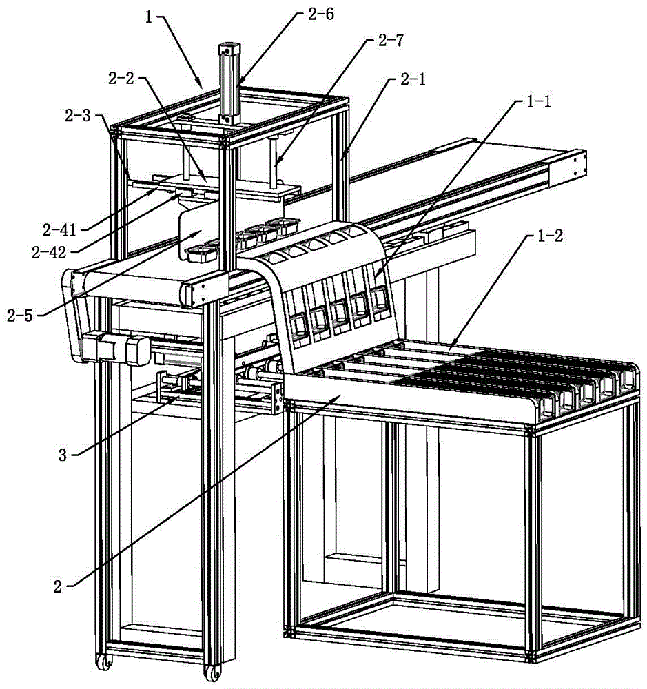
[0039] The pushing and stacking device of this embodiment includes a stacking device 2 , a pushing mechanism 1 and a pushing rod device 3 .

[0040] see figure 1 , push mechanism 1 includes support 2-1, lift cylinder 2-6, lift guide rod 2-7, connecting plate 2-2, push cylinder 2-3, guide rail and push plate 2-5, lift cylinder 2-6 and The lifting guide rod 2-7 is installed on the support 2-1, the connecting plate 2-2 is provided with a guide rod through hole, the lifting guide rod 2-7 passes through the guide rod through hole, and the lifting cylinder 2-6 drives the connecting plate 2-2 along the The lifting guide rod 2-7 moves up and down, and the push plate 2-5 is slidably installed on the connecting plate 2-2 by the guide rail. Block 2-42 is installed on push plate 2-5, pushes cylinder 2-3 and pushes plate 2-5 and drives to connect. In this embodiment, the pushing plate 2-5 includes two parts, one part is a flat plate for directly pushing the cup material, and the other pa...

Embodiment 2

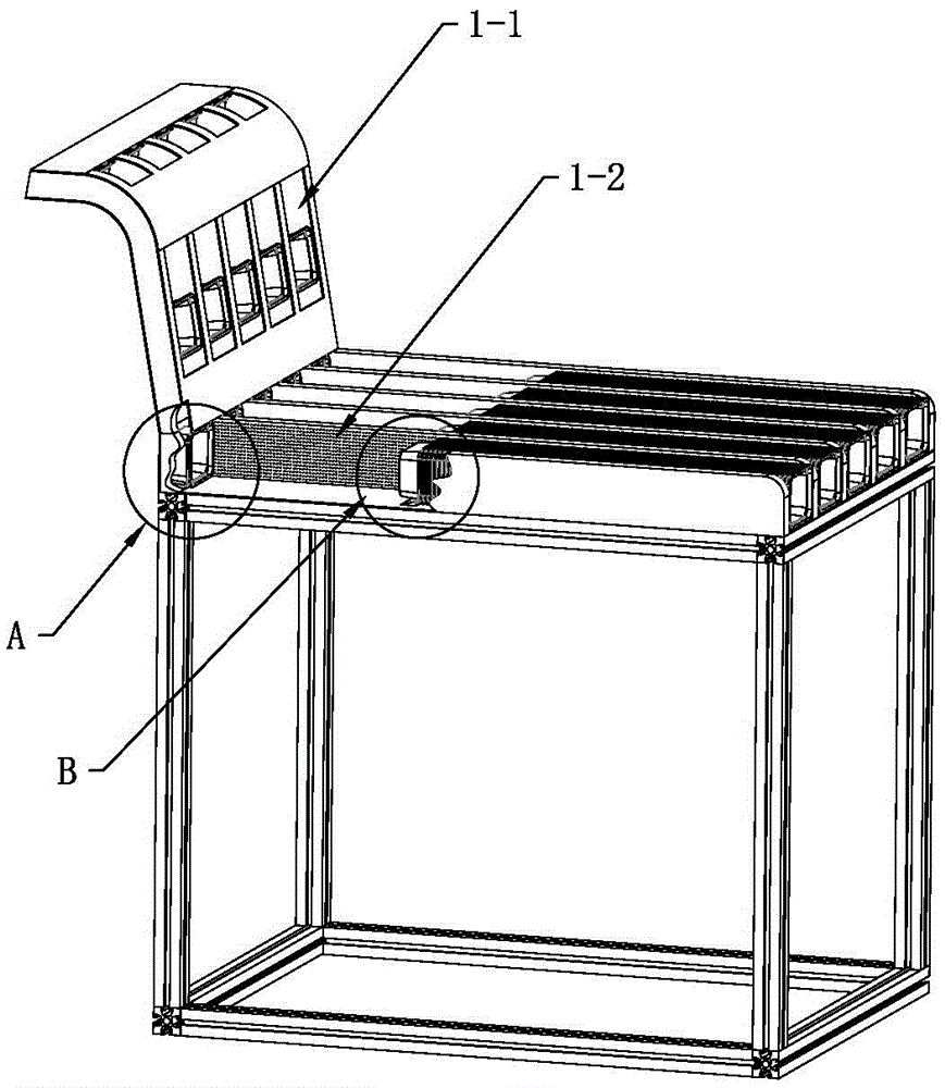
[0046] The main technical solution of this embodiment is basically the same as that of Embodiment 1, and the features not explained in this embodiment are explained in Embodiment 1, and will not be repeated here. In this embodiment, the buffer structure 1-4 of the push-and-stack channel 1-2 is a multi-track deceleration belt, and the deceleration belt can also be used as a bearing bump 1-3.

Embodiment 3

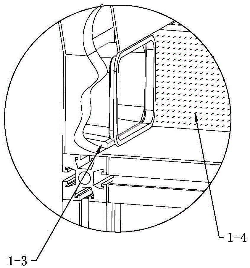
[0048] The main technical solutions of this embodiment are basically the same as those of Embodiment 1 or Embodiment 2, and the features not explained in this embodiment are explained in Embodiment 1 or Embodiment 2, and will not be repeated here. see Image 6 , The push-and-stack channel 1-2 of this embodiment is provided with only one pad bump 1-3, and the pad bump 1-3 is located in the lower front of the blanking opening.


PUM


Abstract

The invention discloses a material pushing and stacking device. The material pushing and stacking device comprises a stacking device, a pushing mechanism and a push rod device. A stacking channel of the stacking device comprises a slide channel and a stacking and pushing channel. The pushing mechanism pushes cup materials into a feeding inlet of the slide channel. The cup materials can creep down along the slide channel under the gravity action of the cup materials and then fall into the stacking and pushing channel from a material falling opening of the slide channel. A push rod of the push rod device pushes the cup materials to advance, and the cup materials are stopped and clamped onto a rim lug. On one hand, the rim lug plays the effect of decelerating and stopping the cup materials; and on the other hand, the bottom of each cup material can be cushioned up so that the next cup material can be stacked smoothly. Compared with the prior art, the material pushing and stacking device has the following main beneficial effects that the degree of automation is high, and human resource cost is reduced; the stacking effect is good, the cup materials are stacked, and meanwhile the entire stacked cup materials can be pushed; and the cup materials can be pushed and stacked at the same time, and thus efficiency is greatly improved.

Description

technical field [0001] The invention relates to the technical field of cup making, in particular to a pushing and stacking device for cup material transportation and processing in the cup making process. Background technique [0002] At present, plastic sheets are thermoformed by a cup making machine into plastic containers, including cups, bowls, boxes and covers, etc., a plastic product used to hold or cover liquid or solid objects, commonly known as: "disposable plastic Cups", "disposable plastic bowls" and other containers, such plastic containers are widely used in all walks of life and in daily life, such as: beverages, yogurt, food cups, butter cups, jelly cups, disposable water cups, instant noodle bowls , ice cream cups or boxes, fast food bowls, etc. [0003] The traditional cup-making machines at home and abroad with thermoforming plastic upper and lower clamping molds, punching, demoulding, blowing cups and ejecting molds cannot realize the function of automatic...

Claims


Application Information

Patent Timeline
Patent Type & Authority Applications(China)
IPC IPC(8): B65G57/10B65G57/16
CPCB65G57/10B65G57/165
Inventor 王昌佑
Owner GUANGDONG LONGXING PACKAGING IND
Why Eureka
Try Eureka