
Vehicle

A vehicle and wheel technology, applied in the field of vehicles, can solve the problems that the driver is difficult to grasp, cannot end the switching of the driving mode, and is complicated.

Inactive Publication Date: 2017-02-22
NTN CORP
View PDF11 Cites 5 Cited by
  • Summary
  • Abstract
  • Description
  • Claims
  • Application Information

AI Technical Summary

Problems solved by technology

That is, there is a problem that even if the front wheels are steered in the direction in which the vehicle travels, that is, in the turning direction, it is not possible to make the posture of the vehicle coincide with the turning direction to perform the steering operation.
However, since actuators are provided to change the length of the tie rods, the distance between the left and right tie rods, or the angle formed by the wheel and the knuckle arm, there are many actuators and the control is complicated.
In addition, the technology described in Patent Document 2 not only has a complicated structure based on this mechanism, but also uses the rotation of the rack bar to steer the wheels, thereby using a plurality of gears
Therefore, shaking is likely to occur, and it is difficult to smoothly turn the wheels.
[0015] In addition, the technology of Patent Document 3 is an example of a conventional four-wheel steering mechanism and can perform rear wheel steering, but it is difficult to perform lateral movement in this mechanism for the same reason as above.
In addition, the technology of Patent Document 4 can perform toe-in adjustment, but on the other hand, it cannot cope with lateral movement of the vehicle, small turns, etc.
[0016] In addition, Patent Document 5 is designed by the applicant to solve the above-mentioned problems of Patent Documents 1 to 4, and is configured such that the driver can freely switch the driving mode between the normal driving mode and the special driving mode by operating the steering wheel. There is the following problem: it is difficult for the driver to grasp the extent to which the steering wheel is operated to end the switching of the driving mode
Moreover, there is a problem that if the steering wheel operation is stopped in a state where the operation is insufficient, the switching of the driving mode cannot be completed.

Method used


Image

  • Vehicle
  • Vehicle
  • Vehicle

Examples


Embodiment Construction

[0039] Embodiments of the vehicle according to the present invention will be described based on the drawings. First, after the steering mechanism of the vehicle and each travel mode are described, switching of the travel mode and information displayed on the display device at this time will be sequentially described.

[0040] (1) For the steering mechanism and each driving mode of the vehicle

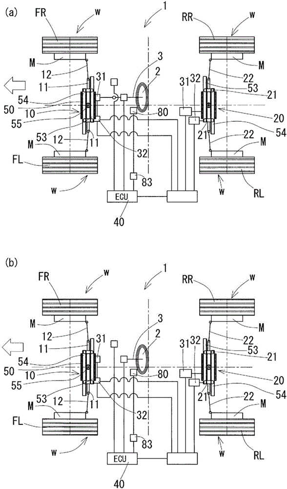
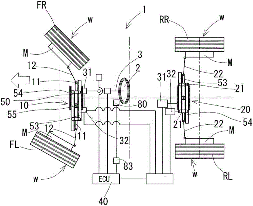
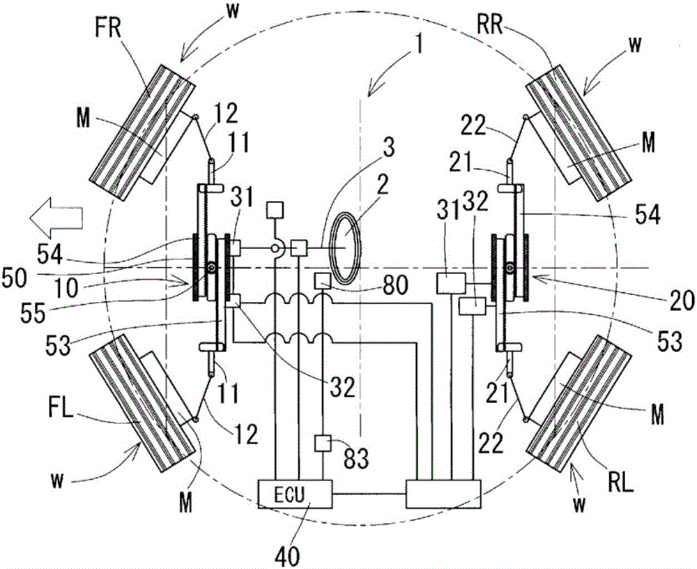
[0041] figure 1 (a) and (b) show the drive system and control path of the vehicle 1 according to the present invention. In this vehicle 1 , front left and right wheels (FL, FR) and rear left and right wheels (RL, RR) are connected to front and rear steering devices 10 , 20 via tie rods 12 , 22 , respectively.

[0042] The respective steering devices 10 and 20 for the front wheels and the rear wheels are provided with two rack bars for steering the left and right wheels w. Hereinafter, the rack bar connected to the wheel w on the left side of the front wheel and the rear wheel with re...


PUM


Abstract

This vehicle (1) is provided with: a steering device (10, 20) that steers the left and right vehicle wheels (w) in opposite directions to the left and right, and that switches the travel mode between a normal travel mode and a special travel mode; a computation means (83) that computes the angle difference between the angle of the left and right vehicle wheels (w) in the normal travel mode or special travel mode and the current angle of the left and right vehicle wheels steered by the steering device (10, 20); and a display device (80) that displays information necessary for a driver to perform a steering operation on the basis of the angle difference computed by the computation means (83).

Description

technical field [0001] The present invention relates to a vehicle provided with a display device for notifying a driver of information related to the steering state of wheels. Background technique [0002] In the structure that steers the wheels using the steering linkage mechanism that connects the left and right wheels (hereinafter, including tires, wheels, hubs, and in-wheel motors, etc., collectively referred to as "wheels"), there is what is called Arkman steering geometry. steering mechanism. This steering mechanism uses tie rods and knuckle arms so that the left and right wheels have the same turning center when the vehicle turns. [0003] As this steering mechanism, for example, there is a structure shown in Patent Document 1 below. This steering mechanism is equipped with a steering link mechanism of the left and right wheels using tie rods and knuckle arms on at least one of the front wheel side or the rear wheel side. The actuator that changes any of the angles...

Claims


Application Information

Patent Timeline
Patent Type & Authority Applications(China)
IPC IPC(8): B62D15/02B60R16/02B62D3/12B62D7/15F16H19/04
CPCF16H19/04B62D7/1509B62D3/126B62D7/159B62D15/0225B62D15/029
Inventor 铃木洋介井口和幸
Owner NTN CORP
Learn More