Touch recognition method, device and electronic equipment

An electronic device and a preset threshold technology, applied in the field of electronics, can solve the problem of occupying display screen space, and achieve a more aesthetic effect of appearance design

Active Publication Date: 2018-09-04
BEIJING XIAOMI MOBILE SOFTWARE CO LTD
View PDF4 Cites 0 Cited by
  • Summary
  • Abstract
  • Description
  • Claims
  • Application Information

AI Technical Summary

Problems solved by technology

Since the integrated circuits (IC) of the infrared light diode and photodiode need to be attached to the printed circuit board (PCB) of the smartphone, and holes must be opened in the glass on the front of the smartphone, because it will occupy the display screen space

Method used


Image

  • Touch recognition method, device and electronic equipment
  • Touch recognition method, device and electronic equipment
  • Touch recognition method, device and electronic equipment

Examples


Embodiment Construction

[0058] Reference will now be made in detail to the exemplary embodiments, examples of which are illustrated in the accompanying drawings. When the following description refers to the accompanying drawings, the same numerals in different drawings refer to the same or similar elements unless otherwise indicated. The implementations described in the following exemplary examples do not represent all implementations consistent with the present invention. Rather, they are merely examples of apparatuses and methods consistent with aspects of the invention as recited in the appended claims.

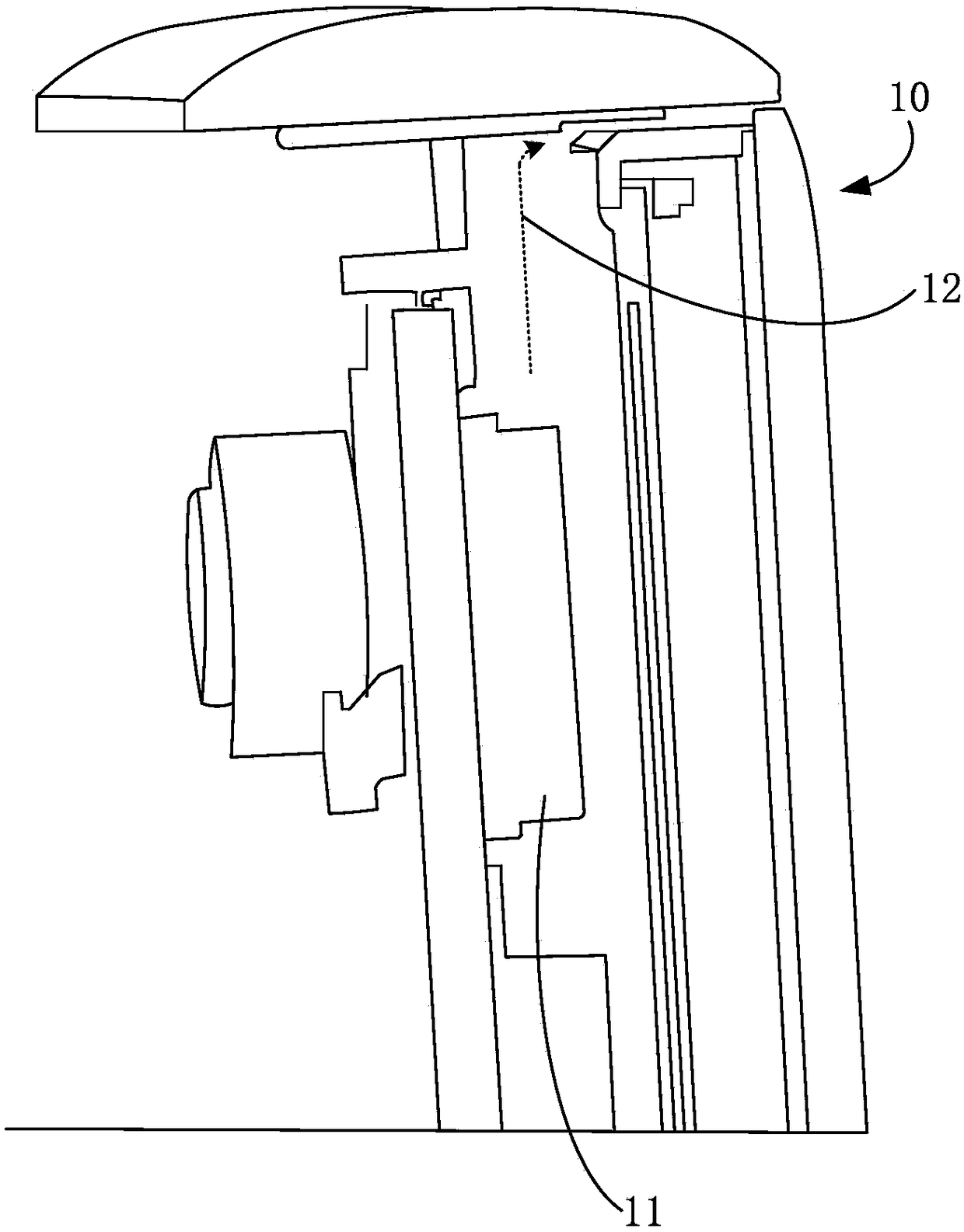
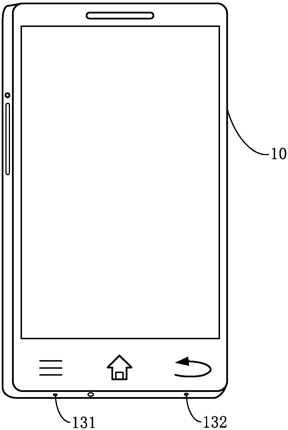
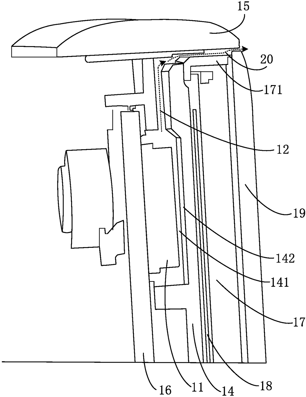
[0059] Figure 1A is a partial three-dimensional structure diagram of a terminal shown according to an exemplary embodiment, Figure 1B yes Figure 1A A schematic diagram of the position of the first perforation on the terminal in the illustrated embodiment; the terminal 10 can be an electronic device with a touch function, such as a smart phone, a tablet computer, etc., such as Figure 1A with ...


PUM


Abstract

The present disclosure relates to a terminal, a touch recognition method, device and electronic equipment. The terminal includes: an ultrasonic transmitter, an ultrasonic signal channel, and a microphone, the ultrasonic transmitter is arranged inside the terminal, and a first perforation is provided on the frame of the terminal for accommodating the microphone; wherein, the ultrasonic transmitter The ultrasonic signal emitted by the transmitter is derived from the interior of the terminal to the surface of the terminal through the ultrasonic signal channel, and the microphone collects the ultrasonic echo signal of the ultrasonic signal, and determines the Whether the terminal is touched. The disclosed technical solution can prevent the ultrasonic transmitter from occupying the space of the glass cover, and ensure that the appearance design of the terminal is more aesthetically pleasing.

Description

technical field [0001] The present disclosure relates to the field of electronic technology, and in particular, to a touch recognition method, device and electronic equipment. Background technique [0002] In related technologies, the anti-mistouch function of smart phones usually requires a proximity sensor. The proximity sensor includes an infrared light diode and a photosensitive diode. During the specific anti-mistouch process, the infrared light wave emits infrared light waves. When it hits the user's face or hair, it will be reflected to the photodiode. The photodiode converts the light wave signal into an electrical signal, and then converts it into a digital signal through a photodiode amplifier (Photo Diode Amplifier). Based on the digital signal, it can identify whether it is in the handheld mode Make a call, and then determine whether to turn on or off the display screen of the smart phone, so as to prevent false touches. Since the integrated circuits (IC) of the...

Claims


Application Information

Patent Timeline
Patent Type & Authority Patents(China)
IPC IPC(8): G06F3/043
CPCG06F3/0433G06F1/1626G06F3/043G06F2200/1631G06F2200/1636H04M1/0202
Inventor 项吉高原崔宏图
Owner BEIJING XIAOMI MOBILE SOFTWARE CO LTD
Why Eureka
Try Eureka