Post-weld heat treatment system beneficial for performance of duplex stainless steel

A technology of duplex stainless steel and post-weld heat treatment, applied in heat treatment furnaces, heat treatment equipment, furnaces, etc., can solve the problems of unsuitability for duplex stainless steel 2205, large influence on the performance of heat exchange tubes, etc., to achieve favorable quenching effect, simple structure, The effect of heat preservation temperature convenience

Inactive Publication Date: 2017-03-08
黄鸣
View PDF0 Cites 0 Cited by
  • Summary
  • Abstract
  • Description
  • Claims
  • Application Information

AI Technical Summary

Problems solved by technology

[0003] Compared with traditional pure ferritic or austenitic stainless steel, duplex stainless steel 2205 has obvious phase transformation during heat treatment, which has a great impact on the performance of heat exchange tub

Method used


Image

  • Post-weld heat treatment system beneficial for performance of duplex stainless steel

Examples


Embodiment 1

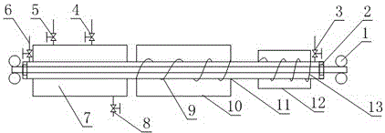
[0026] Such as figure 1 As shown, it is used for solution treatment of duplex stainless steel pipes after welding, including two sets of driving wheels 1 located on the same straight line, anti-oxidation pipe 11 between the two sets of driving wheels 1 and sleeved on the anti-oxidation pipe The cooling chamber 7 and the heat preservation chamber 10 on the 11, the anti-oxidation pipe 11 is a tubular structure with a sealing ring 2 at both ends, the driving wheel set 1 includes two driving wheels, and the two driving wheels There is a gap for accommodating stainless steel pipes between them, the gap is located on the axis of the anti-oxidation pipe 11, and the anti-oxidation pipe 11 is also provided with an air outlet 3 and an air outlet, and the cooling chamber 7 and the heat preservation chamber 10 are located at the air outlet 3 Between the air outlet and the anti-oxidation tube 11 between the heat preservation chamber 10 and the adjacent driving wheel set 1, an intermediate ...

Embodiment 2

[0033] The present embodiment is further limited on the basis of embodiment 1, as figure 1 As shown, in order to control the transmission speed of the duplex stainless steel pipe in the anti-oxidation pipe 11 and control the movement state of the duplex stainless steel pipe, the two sets of driving wheels 1 are located on the same horizontal plane.

[0034] In order to facilitate the uniformity of heating at each point of the duplex stainless steel pipe in the heat preservation chamber 10 and to increase the heating speed, a heat transfer layer is also wound on the surface of the anti-oxidation pipe 11 located in the heat preservation chamber 10, and the resistance heating wire is wound on the heat transfer layer. heat layer.

[0035] In order to facilitate the process parameter control of the heat preservation chamber 10 and the cooling chamber 7, temperature sensors are arranged in the heat preservation chamber 10 and the cooling chamber 7.

[0036] In order to facilitate t...


PUM


Abstract

The invention discloses a post-weld heat treatment system beneficial for performance of duplex stainless steel. The post-weld heat treatment system is used for solid-solution treatment of a welded duplex stainless steel tube. The post-weld heat treatment system comprises two drive wheel sets, an anti-oxidization tube, a cooling room, a thermal-insulation room and a medium-frequency heating coil, wherein the anti-oxidation tube is of a tubular structure with sealing rings at two ends; each drive wheel set comprises two drive wheels; different ends of the anti-oxidization tube are further correspondingly equipped with a gas inlet and a gas outlet; the cooling room is a water storage container with a water inlet and a water outlet; the thermal-insulation room comprises a heat insulating layer and a heating device packaged in the heat insulating layer; the heating device is a resistance heating wire; and a two-way controllable silicon controller is further connected on the resistance heating wire. The post-weld heat treatment system is simple in structure, and facilitates realizing of flowing of all steps for solid-solution treatment of the duplex stainless steel tube, so that rapid warming and shock cooling within short time in a the solid-solution treatment process are realized.

Description

technical field [0001] The invention relates to the field of mechanical engineering heat treatment equipment, in particular to a post-weld heat treatment system that is beneficial to the performance of duplex stainless steel. Background technique [0002] At present, the domestic 2205 stainless steel products include 2205 stainless steel pipes, 2205 duplex stainless steel seamless pipes; 2205 duplex stainless steel plates, 2205 stainless steel bars, forgings, pipe fittings, strips, etc. Early duplex stainless steels were resistant to moderate-strength uniform corrosion and chlorine stress corrosion cracking, but their performance was greatly reduced when used in welded situations. In order to improve this situation, nitrogen is added to duplex stainless steel 2205, which not only improves the corrosion resistance, but also improves the welding performance. Due to the special performance characteristics of 2205 dual-phase steel, it has a wide range of applications, and it is...

Claims


Application Information

Patent Timeline
IPC IPC(8): C21D9/08
Inventor 黄鸣
Owner 黄鸣
Why Eureka
Try Eureka