Friction component bracket

A technology of friction elements and friction clutches, which is applied in the direction of friction clutches, clutches, mechanically driven clutches, etc., can solve the problems of impossibility of rough and fine coordination, and achieve the effect of accurate and sensitive adjustment setting and axial thickness reduction

Active Publication Date: 2017-03-08
SCHAEFFLER TECH AG & CO KG
View PDF6 Cites 7 Cited by
  • Summary
  • Abstract
  • Description
  • Claims
  • Application Information

AI Technical Summary

Problems solved by technology

However, individual volume flows can thus only be determined roughly, fine coordination is almost impossible

Method used


Image

  • Friction component bracket
  • Friction component bracket

Examples


Embodiment Construction

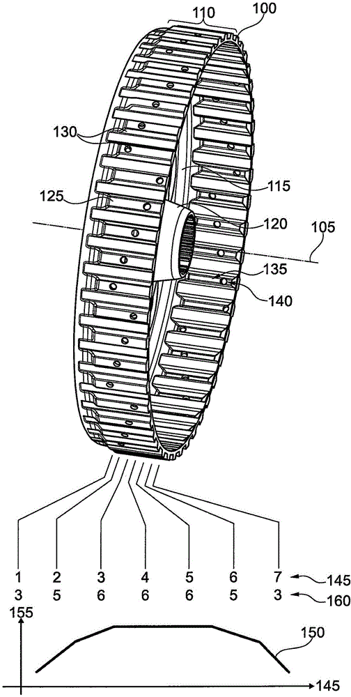
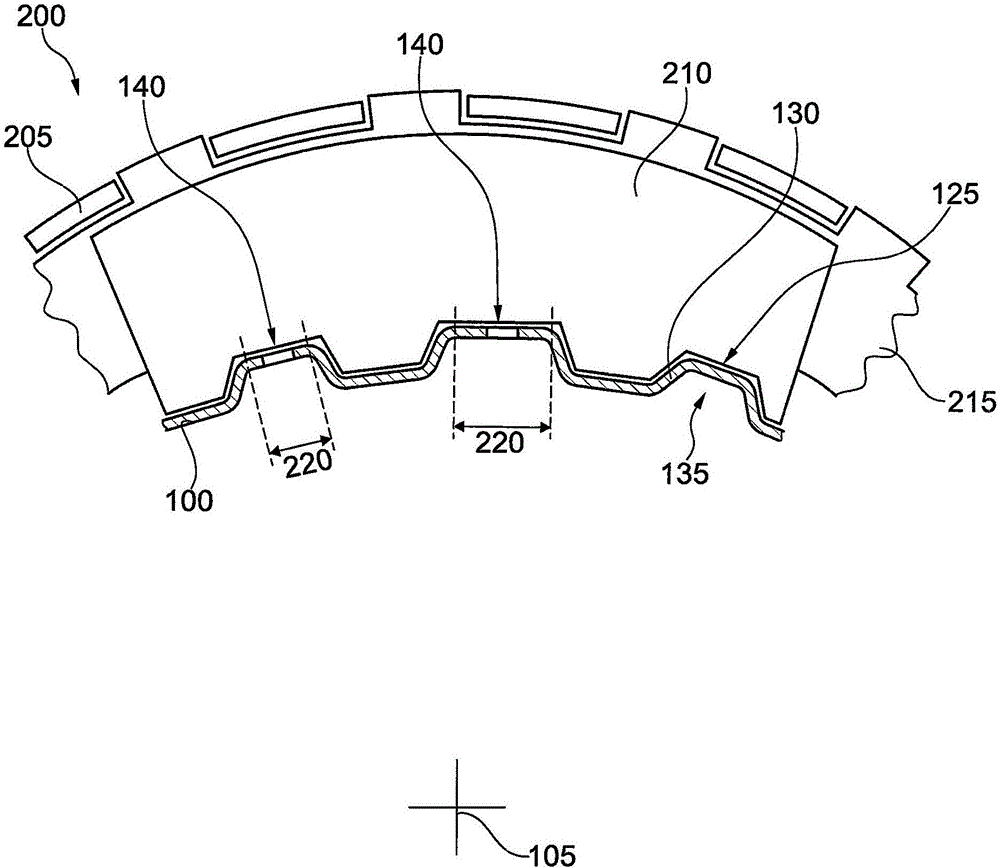
[0021] figure 1 An inner carrier 100 for a friction clutch is shown. The inner carrier 100 has an axis of rotation 105 about which the inner carrier is generally mounted so as to be rotatable. The axial section 110 extends in the axial direction at a predetermined radial distance from the axis of rotation 105 . Preferably a radial section 115 adjoins the axial end of the section 110 in one piece, said radial section extends radially inwards and is further preferably fastened to the hub 120 in a torque-locking manner. The axial section 110 can be produced from a material of substantially uniform thickness, in particular from sheet metal, for example by deep drawing, embossing or stamping. The radial sections 115 can be produced from the same sheet material. The individual teeth 125 are formed on the axial section 110 , the side walls 130 of which extend in the axial and radial directions. as below reference figure 2 As explained in more detail, the toothing 125 or its sid...


PUM


Abstract

A friction component bracket for a multi-disc friction clutch comprises a rotation axis; and an axial section with teeth, wherein the tooth has a sidewall that extends in an axial direction and a radial direction and is used for engaging with the friction component in a shape engagement manner, wherein each tooth is provided with a radial projection at radial inside part of the axial section. The radial outer sections of at least some teeth are respectively provided with a channel opening for allowing radial penetration of fluid. Hereon, different teeth have different extension dimensions in the circumferential direction. Different volume flows of fluid are obtained through the channel openings of the teeth.

Description

technical field [0001] The invention relates to a friction element bracket. In particular, the invention relates to a friction element carrier for a multidisk friction clutch, for example in a drive train of a motor vehicle. Background technique [0002] The friction clutch comprises one or more first friction partners and one or more second friction partners, which are mounted rotatably about a common axis of rotation. The first friction element is in a positive engagement with the first carrier, and the second friction element is in a positive engagement with the second carrier. Torque can be transmitted between the two supports if the friction elements are pressed axially close to one another. [0003] The force transmission between the friction element and the associated carrier is usually produced by toothing, which allows an axial movement of the friction element. If the friction clutch is gradually closed, the rotational speeds of the two carriers gradually adapt t...

Claims


Application Information

Patent Timeline
Patent Type & Authority Applications(China)
IPC IPC(8): F16D13/60F16D13/58
CPCF16D13/58F16D13/60F16D13/683F16D13/72F16D2300/0214
Inventor T·奥萨德尼克
Owner SCHAEFFLER TECH AG & CO KG
Why Eureka
Try Eureka