Grid driving unit and driving method thereof, grid driving circuit, and display apparatus

A gate drive and circuit technology, applied in static indicators, instruments, etc., can solve the problems that the output signal of the gate drive unit is not stable enough, the light emitting diode display device cannot display stably, and the pixel progressive scan drive control is not possible. To achieve the effect of improving the display effect, improving the display stability, and smoothing the waveform curve

Active Publication Date: 2017-03-29
BOE TECH GRP CO LTD +1
View PDF5 Cites 5 Cited by
  • Summary
  • Abstract
  • Description
  • Claims
  • Application Information

AI Technical Summary

Problems solved by technology

[0003] However, in many existing gate drive circuits, the output signal of the gate drive unit is not stable enough, such as usually showing that the waveform curve of the output signal of the gate drive unit is not smooth enough; The amplitude of the input signal waveform of the gate drive unit of the signal is greatly different, which leads to the inability of the gate drive circuit to stably perform normal progressive scan drive control on the pixels, which in turn causes the liquid crystal display device (LCD) using the gate drive circuit to and organic light-emitting diode (OLED) display devices cannot display stably

Method used


Image

  • Grid driving unit and driving method thereof, grid driving circuit, and display apparatus
  • Grid driving unit and driving method thereof, grid driving circuit, and display apparatus
  • Grid driving unit and driving method thereof, grid driving circuit, and display apparatus

Examples


Embodiment 1

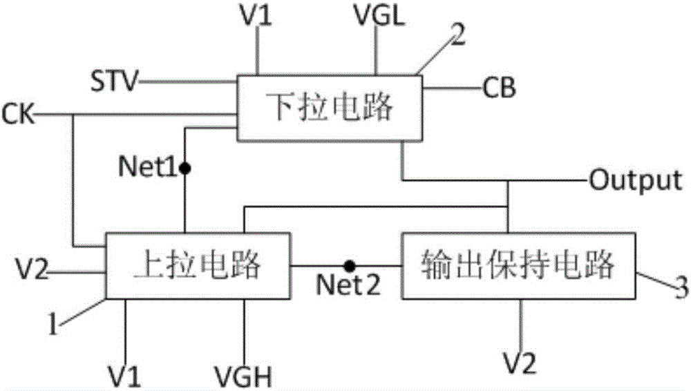
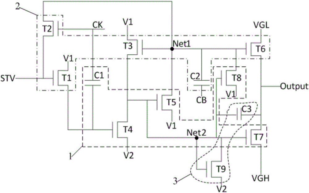
[0043] This embodiment provides a gate drive unit, such as figure 1 As shown, it includes a pull-up circuit 1 and a pull-down circuit 2, and also includes an output holding circuit 3. The pull-up circuit 1, the pull-down circuit 2 and the output holding circuit 3 are connected to the output terminal Output of the gate drive unit; the pull-up circuit 1 and the output The holding circuit 3 is connected to the pull-up node Net2; the pull-up circuit 1 and the pull-down circuit 2 are connected to the pull-down node Net1; the pull-down circuit 2 is connected to the low potential terminal VGL and the first potential terminal V1, and the pull-up circuit 1 is connected to the high potential terminal VGH, the first potential terminal A potential terminal V1 and a second potential terminal V2; the output holding circuit 3 is connected to the second potential terminal V2. The pull-up circuit 1 is used to make the output terminal Output output the gate scanning signal under the control of ...

Embodiment 2

[0060] This embodiment provides a gate drive unit. The difference from Embodiment 1 is that the first potential terminal is a low potential, and the second potential terminal is a high potential; the first transistor, the second transistor, the third transistor, the fourth The transistors, the fifth transistor, the sixth transistor, the seventh transistor, the eighth transistor and the ninth transistor are all N-type transistors.

[0061] Other circuit structures of the gate driving unit in this embodiment are the same as those in Embodiment 1.

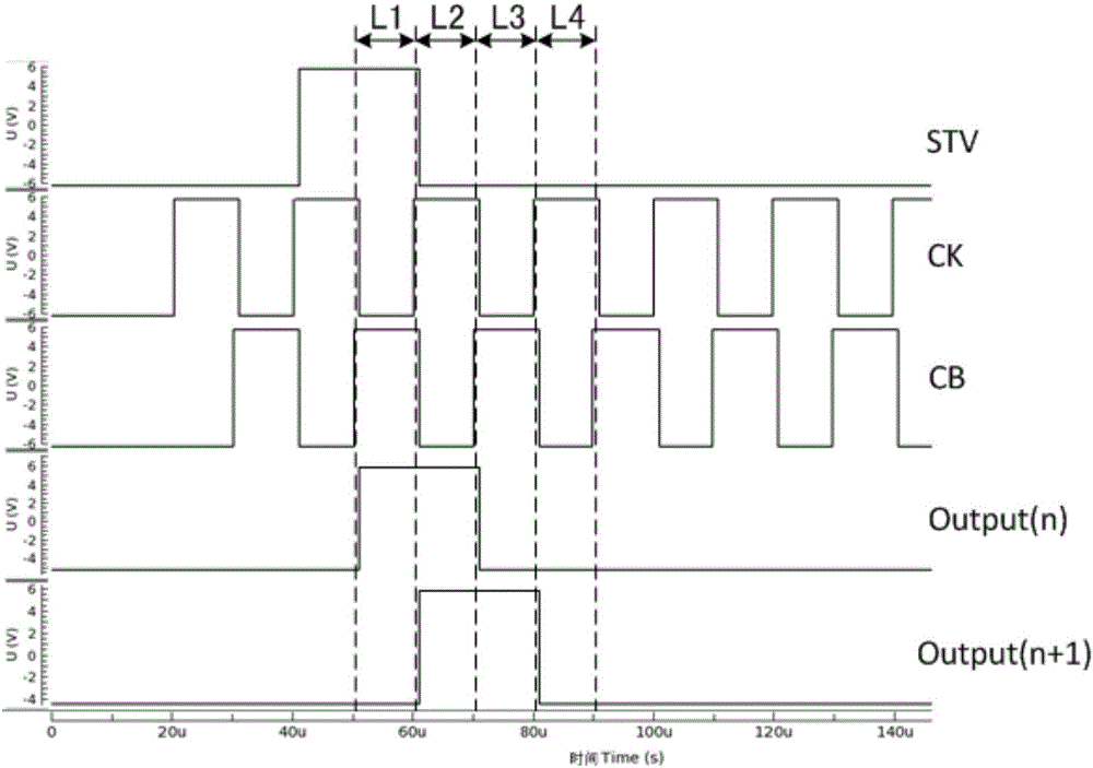
[0062] Correspondingly, based on the above circuit structure of the gate driving unit in this embodiment, this embodiment also provides a driving method of the gate driving unit, which is different from the driving method in Embodiment 1, as Figure 5 As shown, in the pull-up phase L1, the output hold phase L2, the pull-down phase L3 and the pull-down hold phase L4, the potentials of the trigger signal STV, the first control signal CK...

Embodiment 3

[0066] This embodiment provides a gate driving circuit, including the gate driving unit in Embodiment 1 or 2.

[0067] By using the gate drive unit in Embodiment 1 or 2, the scan drive of the gate by the gate drive circuit is more stable.


PUM


Abstract

The invention provides a grid driving unit and a driving method thereof, a grid driving circuit, and a display apparatus. The grid driving unit comprises a pull-up circuit and a pull-down circuit, and further comprises an output holding circuit, wherein the pull-up circuit is used for enabling an output end to output grid scanning signals under the control of trigger signals, first control signals and second control signals; the output holding circuit is used for keeping the output end outputting the grid scanning signals under the control of the previous control signals; and the pull-down circuit is used for resetting the grid scanning signals under the control of the previous control signals and enabling the grid scanning signals to maintain a reset state within a set duration. The grid driving unit provided by the invention can enable the grid scanning signals output by the output end to be more stable, compared to the prior art, waveform curves of the grid scanning signals are smoother, waveform amplitude differences between the grid scanning signals and corresponding input signals generating the grid scanning signals are reduced, and the grid driving unit can perform scanning driving more stably.

Description

technical field [0001] The present invention relates to the field of display technology, in particular to a gate drive unit, a drive method thereof, a gate drive circuit and a display device. Background technique [0002] Currently, liquid crystal display (LCD) and organic light emitting diode (OLED) display devices are still the mainstream products of flat panel display. In a liquid crystal display device and an actively driven OLED display device, a thin film transistor (ThinFilm Transistor: TFT for short) is usually used to control each pixel so as to realize image display. Pixel control includes row control and column control. Row control is usually a gate drive circuit (GOA), which realizes row-by-row scanning of pixels; column control is usually a data drive circuit, which realizes the transmission of display data of pixels. A traditional gate drive circuit is composed of multiple gate drive units cascaded, and each gate drive unit has the same circuit. [0003] Howe...

Claims


Application Information

Patent Timeline
Patent Type & Authority Applications(China)
IPC IPC(8): G09G3/20G09G3/3266G09G3/36
CPCG09G3/20G09G3/3266G09G3/3677G09G2300/0408G09G2300/0852G09G2310/0267G09G2310/061
Inventor 王博
Owner BOE TECH GRP CO LTD
Why Eureka
Try Eureka