Electronic device shell

A technology for electronic devices and casings, which is applied in the direction of support structure installation, casing/cabinet/drawer components, support structures on hinges/pivots, etc., which can solve problems such as inconvenience for maintenance personnel

Inactive Publication Date: 2017-03-29
HONG FU JIN PRECISION IND WUHAN CO LTD +1
View PDF5 Cites 2 Cited by
  • Summary
  • Abstract
  • Description
  • Claims
  • Application Information

AI Technical Summary

Problems solved by technology

This brings inconvenience to th

Method used


Image

  • Electronic device shell
  • Electronic device shell
  • Electronic device shell

Examples


Embodiment Construction

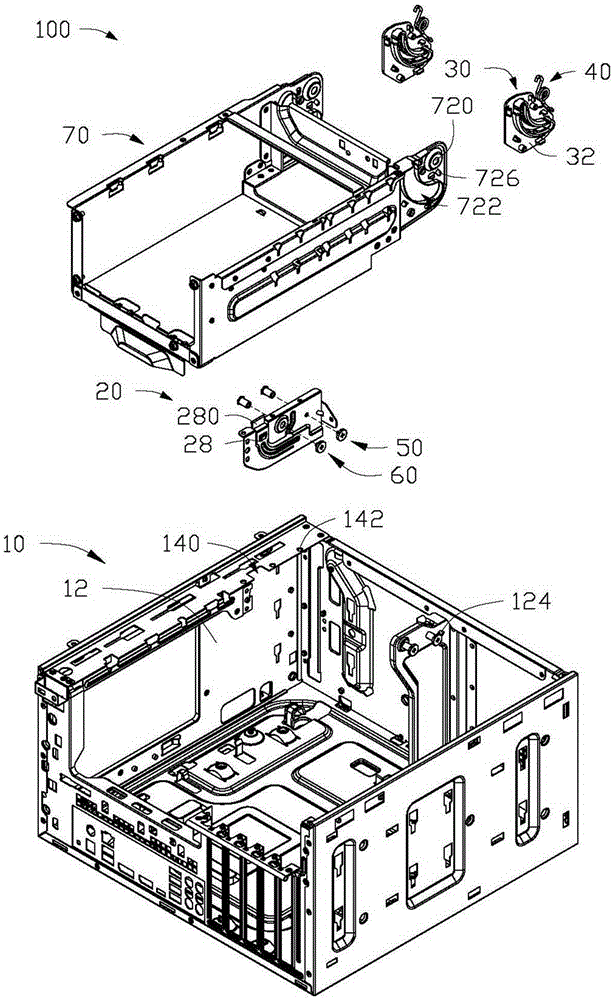
[0026] see figure 1 , in a preferred embodiment of the present invention, an electronic device housing 100 includes a casing 10, a positioning member 20, two mounting members 30, two supporting members 40, a rotating shaft 50, a rotating member 60 and a bracket 70.

[0027] The casing 10 includes two substantially parallel side panels 12 and a first edge 14 . The first edge 14 extends from a side panel 12 and is perpendicular to the side panel 12 . Each side panel 12 defines a mounting hole 120 . The first edge 14 is provided with a relief portion 140 and a plurality of first locking holes 142 . A first notch 124 is disposed on the side panel 12 away from the first edge 14 .

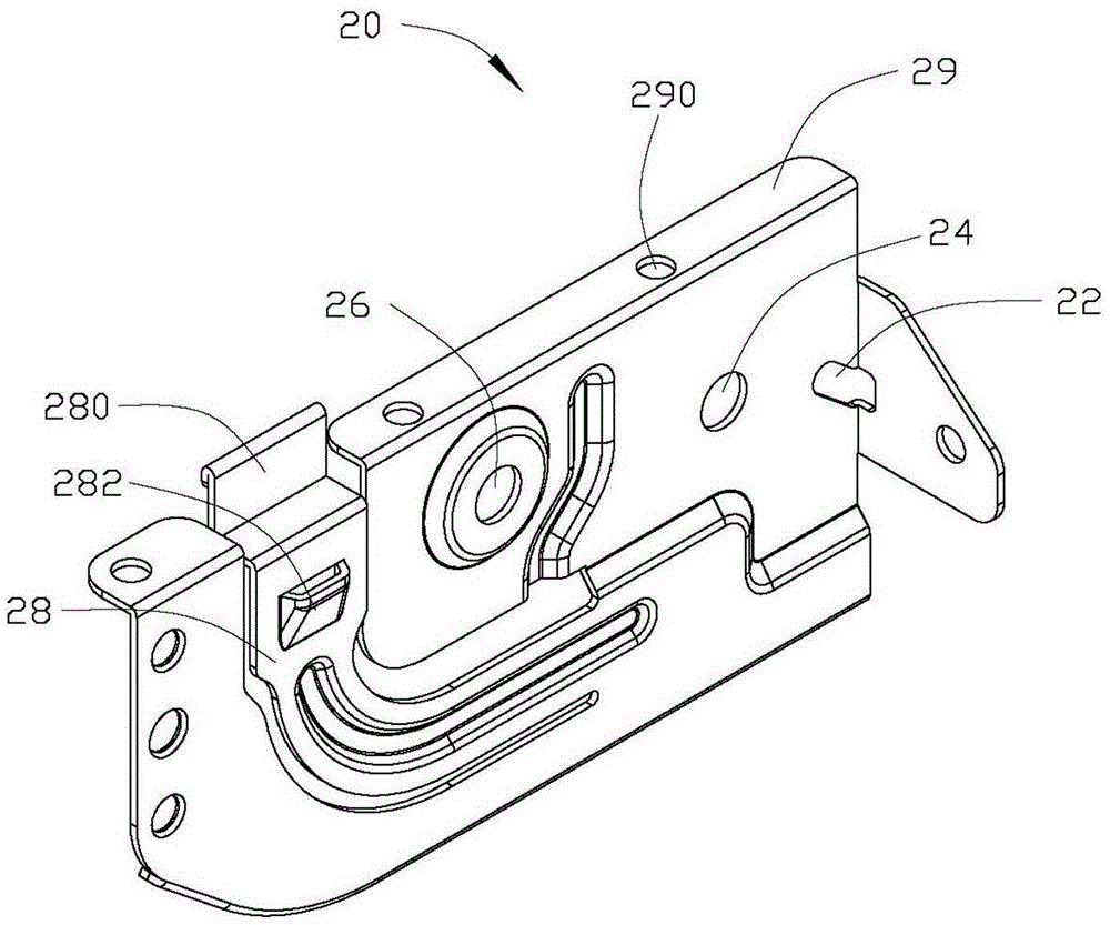
[0028] read on figure 2 , the positioning member 20 is provided with a first fixing hole 24 and a second fixing hole 26 . An opening 22 is also defined on the edge of the positioning member 20 . The positioning member 20 further includes an elastic piece 28 and a second folded edge 29 . The elas...


PUM


Abstract

The invention relates to an electronic device shell. The electronic device shell includes a shell and a bracket mounted in the shell, wherein the bracket is used for fixing a power source. The electronic device shell further comprises a rotation shaft and a supporting component which sleeves the rotation shaft; the bracket is rotationally fixed onto the shell through the rotation shaft; two opposite ends of the supporting component are fixed onto the bracket and the shell respectively; and when the bracket rotates along a direction relative to the shell, the supporting component is deformed so as to support the bracket, so that the bracket can be prevented from rotating along a second direction opposite to the first direction.

Description

technical field [0001] The invention relates to an electronic device casing, in particular to an electronic device casing capable of conveniently positioning a power supply fixing frame. Background technique [0002] With the development of science and technology, electronic devices are used more and more frequently in daily life, and are developing towards the direction of miniaturization. As an important part of the electronic device, the power supply is usually fixed above the mainboard by screws in order to reduce the occupied space. However, when the main board or parts on the main board need to be repaired or replaced, the power supply needs to be removed to have enough space for repairing or replacing the main board. After the maintenance of the main board or parts on the main board is completed, the power supply needs to be fixed on the main board again. This brings inconvenience to the work of maintenance personnel. Contents of the invention [0003] In view of...

Claims


Application Information

Patent Timeline
IPC IPC(8): H05K5/02
CPCH05K7/16
Inventor 彭勇韩和涛谭军华荆效忠林益生翟翀王良津
Owner HONG FU JIN PRECISION IND WUHAN CO LTD
Why Eureka
Try Eureka