Fault injection circuit, method and device

A fault injection and circuit technology, applied in the direction of measuring devices, measuring electricity, measuring electrical variables, etc., can solve problems such as failure to use half-duplex communication fault injection circuits

Active Publication Date: 2019-02-19
BEIJING RUNKE GENERAL TECH
View PDF9 Cites 0 Cited by
  • Summary
  • Abstract
  • Description
  • Claims
  • Application Information

AI Technical Summary

Problems solved by technology

[0004] In view of this, the present invention provides a fault injection circuit, method and device to overcome the problem that there is no fault injection circuit applied to half-duplex communication in the prior art

Method used


Image

  • Fault injection circuit, method and device
  • Fault injection circuit, method and device
  • Fault injection circuit, method and device

Examples


Embodiment Construction

[0042] The following will clearly and completely describe the technical solutions in the embodiments of the present invention with reference to the accompanying drawings in the embodiments of the present invention. Obviously, the described embodiments are only some, not all, embodiments of the present invention. Based on the embodiments of the present invention, all other embodiments obtained by persons of ordinary skill in the art without making creative efforts belong to the protection scope of the present invention.

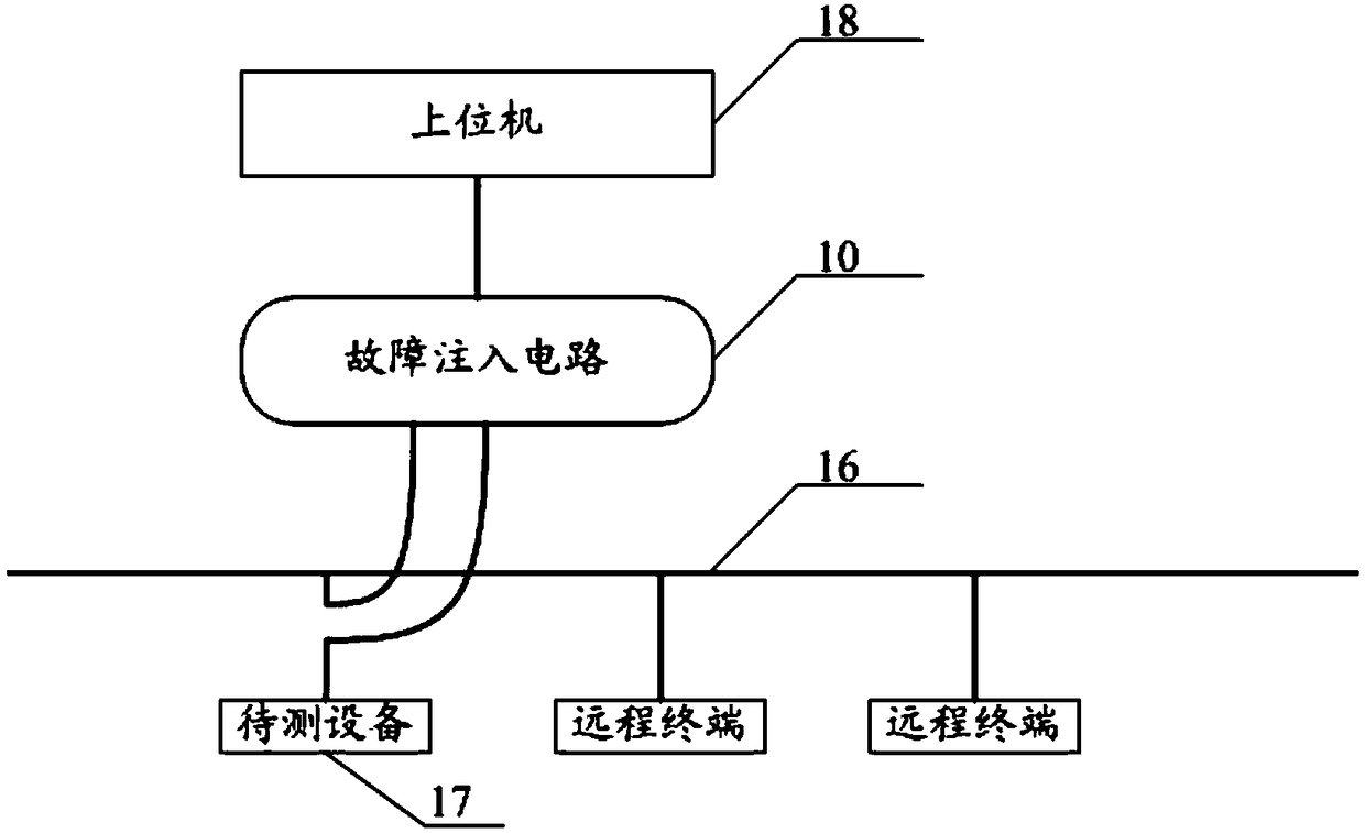
[0043] An embodiment of the present invention provides a fault injection circuit. When the fault injection circuit performs fault injection on the device under test, it needs to be connected with the device under test as follows. Please refer to figure 1 , is a schematic diagram of a connection between a fault injection circuit and a device under test provided by an embodiment of the present invention.

[0044] The bus includes multiple couplers connected in s...


PUM


Abstract

The embodiment of the invention provides a fault injection circuit, method and apparatus. The method includes: receiving a message from a bus through a first transformer, a first selection switch, a first input pin of a first signal processing module, a second output pin of the first signal processing module, and a first input pin of a fault injection module; sending the message from the bus through a second output pin of the fault injection module, a first input pin and a second output pin of a second signal processing module, and a second selection switch; receiving a message from a to-be-detected device through a second transformer, the second selection switch, a second input pin and a first output pin of the second signal processing module, and a second input pin of the fault injection module; and sending the message from the to-be-detected device through a first output pin of the fault injection module, a second input pin and a first output pin of the first signal processing module, and the first selection switch. Therefore, half-duplex communication of data on lines is realized.

Description

technical field [0001] Embodiments of the present invention relate to the technical field of fault injection, and more specifically relate to a fault injection circuit, method and device. Background technique [0002] Fault injection is to use a certain strategy to introduce faults into the device under test to accelerate the occurrence of faults and errors of the device under test. By observing and analyzing the working status of the device under test when the fault is injected, the reliability of the device under test is evaluated. sex and stability etc. [0003] In the prior art, when performing fault injection, the fault injection circuit needs to be connected in series between the bus and the device under test. At present, this fault injection circuit is only suitable for simplex communication, that is, there is currently no fault injection circuit for half-duplex communication. . Contents of the invention [0004] In view of this, the present invention provides a f...

Claims


Application Information

Patent Timeline
Patent Type & Authority Patents(China)
IPC IPC(8): G01R31/02
CPCG01R31/50
Inventor 赵志强
Owner BEIJING RUNKE GENERAL TECH
Why Eureka
Try Eureka