Integrated ceramic resistor relay box

A technology of ceramic resistors and relay boxes, applied in circuits, electrical switches, electrical components, etc., can solve the problems of poor reliability of winding resistors, unsupported resistor bodies, and large heat generation, to ensure sealing and vibration performance, improve Product reliability, the effect of convenient production line production

Active Publication Date: 2017-04-05
XIAMEN HONGFA AUTOMOTIVE ELECTRONICS
View PDF7 Cites 0 Cited by
  • Summary
  • Abstract
  • Description
  • Claims
  • Application Information

AI Technical Summary

Problems solved by technology

[0003] 1. Because of the high heat generation, the resistor body has no support and is easy to deform;
[0004] 2. Because the resistor body is easily deformed, the reliability of the wire-wound resistor

Method used


Image

  • Integrated ceramic resistor relay box
  • Integrated ceramic resistor relay box
  • Integrated ceramic resistor relay box

Examples


Example Embodiment

[0044] The present invention will be further described below through specific embodiments.
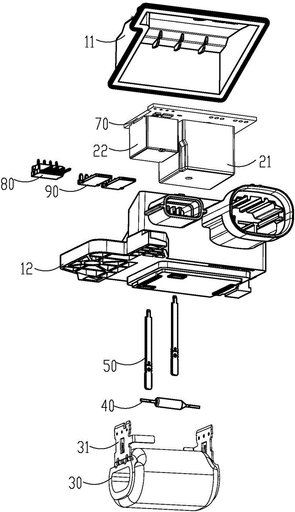
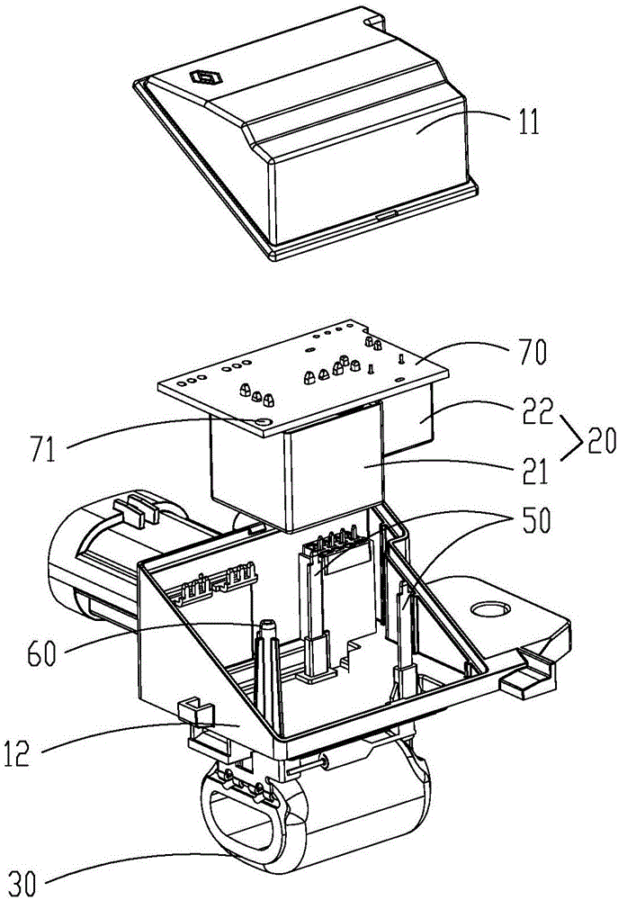
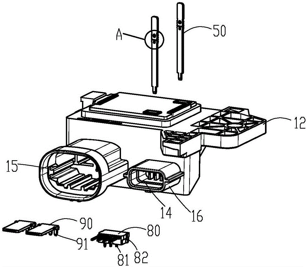
[0045] Reference Figure 1 to Figure 14 , The integrated ceramic resistance relay box includes a housing 10 and an electromagnetic relay group 20 located in the housing 10, a PCB board 70, a ceramic resistor 30, a temperature fuse 40, and two metal conductive connecting pieces 50. The electromagnetic relay group 20 includes a high-speed fan control relay 21 and a low-speed fan control relay 22. The electromagnetic relay group 20 can also be replaced by MOS tubes or other electronic switching elements, which are welded on the PCB board 70. The housing 10 includes an upper housing 11 and a lower housing 12. The upper housing 11 and the lower housing 12 form a glue groove 13 at the junction of the upper housing 11 and the lower housing 12, and the glue groove 13 is formed at the joint after the upper housing 11 and the lower housing 12 are assembled. The groove is used to dispense glue in t...


PUM


Abstract

An integrated ceramic resistor relay box comprises housing and an electromagnetic relay set located in the housing, a PCB, a ceramic resistor, a thermal fuse and two metal conductive connection sheets. The electromagnetic relay is welded on the PCB, the ceramic resistor is fixed on the housing, one ends of the metal conductive connection sheets are respectively electrically connected with one end of the ceramic resistor and one end of the thermal fuse, the other ends of the metal conductive connection sheets are connected with the PCB, and the integration injection moulding assembling is employed between the two metal conductive connection sheets and the housing; and the other end of the thermal fuse is electrically connected with the other end of the ceramic resistor. The integrated ceramic resistor relay box employs the integration design of employing the ceramic resistor to integrate the electronic devices such as the electromagnetic relay set and the thermal fuse to miniaturize the products and improve the product reliability; and a simple and reliable installation structure is employed between each part to improve the production efficiency.

Description

technical field [0001] The invention relates to the field of relays, in particular to an integrated ceramic resistance relay box integrating multiple electronic components. Background technique [0002] In the automotive field, the traditional cooling fan control mostly adopts a wire-wound resistor design, and each electronic component such as an electromagnetic relay, a thermal fuse, etc. is set separately, which mainly has the following disadvantages: [0003] 1. Because of the high heat generation, the resistor body has no support and is easy to deform; [0004] 2. Because the resistor body is easily deformed, the reliability of the wire-wound resistor is poor; [0005] 3. Because the wire-wound resistor is directly exposed to the air and works in a high-temperature and high-humidity environment, it is easy to be oxidized, resulting in a short product life. Contents of the invention [0006] The main purpose of the present invention is to overcome the above-mentioned ...

Claims


Application Information

Patent Timeline
IPC IPC(8): H01H89/04H01H9/04
CPCH01H9/04H01H89/04
Inventor 李进廷陈可璜朱德强
Owner XIAMEN HONGFA AUTOMOTIVE ELECTRONICS
Why Eureka
Try Eureka