Bladder continuous flusher

A irrigator and bladder technology, which is applied in the field of medical equipment, can solve the problems of leakage of drainage fluid, increase of urinary tract infection, inconvenience of drainage fluid outflow speed, etc., reduce the number of times of dumping drainage fluid and reduce the risk of urinary tract infection Probability and observation effect are better and more intuitive

Inactive Publication Date: 2017-04-26
SUZHOU SCI&TECH TOWN HOSPITAL
View PDF10 Cites 1 Cited by
  • Summary
  • Abstract
  • Description
  • Claims
  • Application Information

AI Technical Summary

Problems solved by technology

[0003] At present, drainage bags are often used in the clinical nursing or monitoring process, but the most commonly used drainage bags have a volume of 500mL. When applied to continuous bladder irrigation care, new drainage bags must be replaced frequently to ensure the collection of irrigation fluid, which brings a great deal of work intensity to the nursing staff, and sometimes causes leakage of drainage fluid when replacing the drainage bag Situations occur that are prone to contamination or unnecessary infection
[0004] On the other hand, during the drainage process, it is necessary to observe the flow rate of the drainage fluid from the body to control the drainage process, but the current bladder irrigator is not convenient to observe the outflow rate of the drainage fluid, usually the drainage tube is taken out of the collection box , look at the drip rate of the drainage tube, this method not only causes inconvenience to the medical staff, but also exposes the drainage fluid, the flusher cannot be sealed, and increases the chance of urinary tract infection

Method used


Image

  • Bladder continuous flusher
  • Bladder continuous flusher
  • Bladder continuous flusher

Examples


Embodiment 1

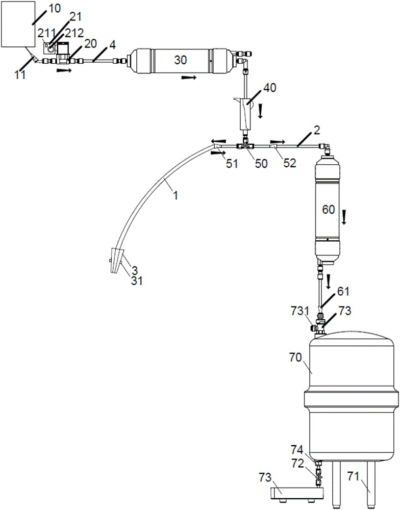
[0033] like figure 1 As shown, the present invention provides a continuous bladder irrigator. Fluid storage bag 10 is filled with flushing liquid, and flow regulator 40 communicates with fluid storage bag 10 through liquid delivery tube 4. A drip funnel 30, an infusion pump 20 is also arranged on the liquid delivery pipe 4, and the infusion pump 20 is connected on the pipeline between the first drip funnel 30 and the liquid storage bag 10, and a puncture joint 11 is provided at one end of the liquid delivery pipe 4, and The liquid pipe 4 communicates with the liquid storage bag 10 through a puncture joint 11 .

[0034] The output end of the flow regulator 40 is provided with a three-way cock valve 50, and the flow regulator 40 is used to adjust the input flow rate of the flushing liquid. The output end of the two interfaces is provided with a first joint 51, and the drainage cavity connector 3 communicates with the first joint 51 through the flushing tube 1. The first joint 5...

Embodiment 2

[0043] On the basis of Embodiment 1, the upper end of the collection box 70 is provided with a collection box joint 73, and the output end of the second dropping funnel 60 is connected to the collection box joint 73 through the third joint 61, and the third joint 61 is convenient for the drain pipe 2 and the collection box. The connection of the tank joint 73 is provided with a pressure-controlled pressure relief valve 731 on the collection tank joint 73. Under normal circumstances, the pressure-controlled pressure relief valve 731 is in a normally closed state. When the liquid is discharged to the collection tank 70, the When the pressure increases, when the air pressure in the collection box 70 is higher than the set value of the pressure-controlled pressure relief valve 731, the pressure-controlled pressure relief valve 731 is pushed open to release the pressure, so that the air pressure in the collection box 70 is maintained within the normal range without affecting Normal ...

Embodiment 3

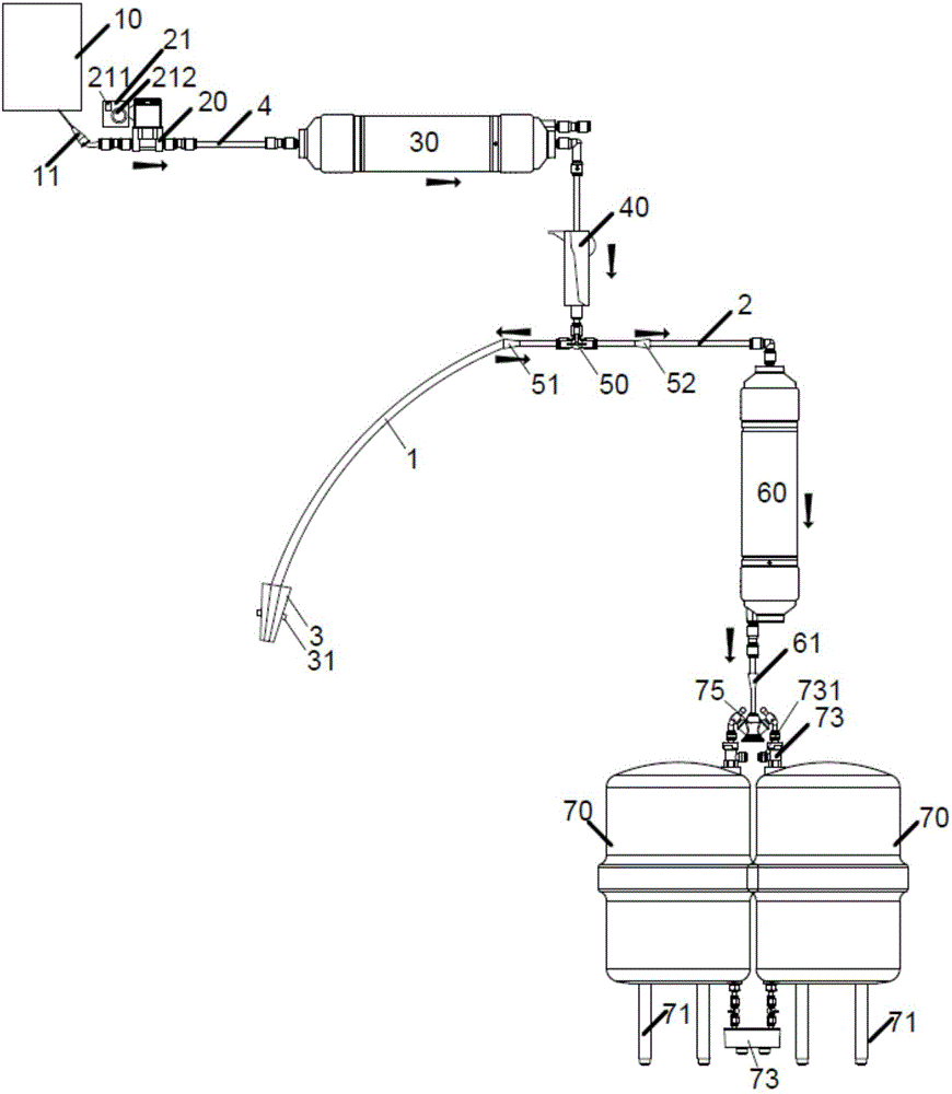
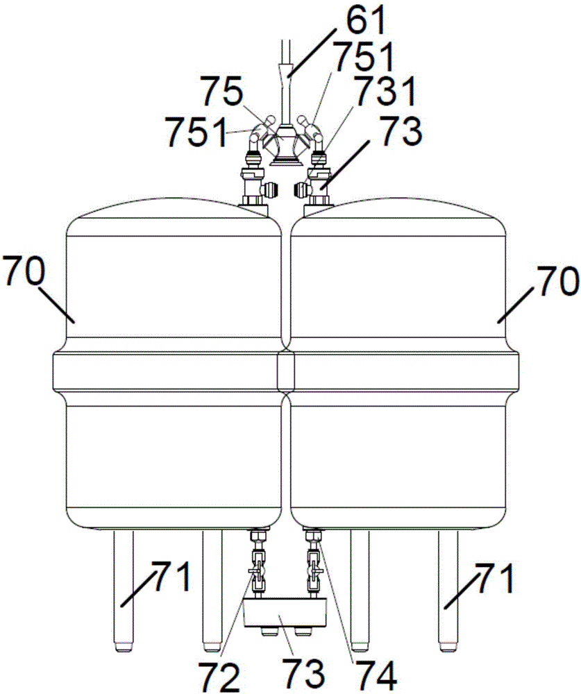
[0045] The difference with Embodiment 2 is that, as Figure 2-3 As shown, the lower end of the third joint 61 is connected with a double drain valve 75, and the lower end of the double drain valve is equipped with two collection tanks 70, and the first drain valve 751 of the double drain valve is connected to a collection tank joint at the upper end of the collection tank 70 73, the second drain valve 751 is connected to the collection box connector 73 on the upper end of another collection box 70, and the two collection boxes 70 can collect the drainage fluid in turn to increase the collection capacity of the drainage fluid, and the dump switch 72 at the lower end of the two collection boxes 70 can They are connected together at one place, and the liquid storage bottle 73 is connected to the dump switch 72 to realize the continuous discharge of the collection box 70, which further improves the drainage efficiency of the collection box 70 and realizes the continuous operation o...


PUM


Abstract

The present invention discloses a bladder continuous flusher. The bladder continuous flusher comprises a liquid storage bag, a flow regulator, a drainage cavity connection head and a collection box; the flow regulator is connected with the liquid storage bag through a liquid feeding pipe; the liquid feeding pipe is provided with a first drip chamber; the output end of the flow regulator is provided with a three-way plug valve; the drainage cavity connection head is communicated with the second interface of the three-way plug valve through a flushing pipe; the drainage cavity connection head is provided with a plug cock used for locking the drainage cavity connection head; the collection box is communicated with the third interface of the three-way plug valve through a liquid discharge pipe; the collection box is a transparent cylinder with scale marks; the lower end of the collection box is provided with a liquid discharge opening; the liquid discharge pipe is provided with a second drip chamber; and the second drip chamber is communicated between the collection box and the third interface of the three-way plug valve. According to the bladder continuous flusher of the invention, a drainage liquid collection capability is additionally achieved, and the liquid discharge pipe is provided with the drip chamber, so that the out-flow speed of a drainage liquid can be observed through the drip chamber, and therefore, conveniences can be brought to medical staff.

Description

technical field [0001] The invention relates to the technical field of medical equipment. More specifically, the present invention relates to a continuous bladder irrigator. Background technique [0002] Generally, bladder flushing is one of the common nursing techniques in urology. Its purpose is to dilute the blood leaking from the bladder through flushing with a large amount of normal saline, so as to prevent blood from coagulating and blocking the urethra; at the same time, antibiotics can also be used to prevent or treat bacterial infection. Cystitis. [0003] At present, drainage bags are often used in the clinical nursing or monitoring process, but the most commonly used drainage bags have a volume of 500mL. When applied to continuous bladder irrigation care, new drainage bags must be replaced frequently to ensure the collection of irrigation fluid, which brings a great deal of work intensity to the nursing staff, and sometimes causes leakage of drainage fluid when ...

Claims


Application Information

Patent Timeline
IPC IPC(8): A61M3/02
CPCA61M3/022A61M3/0254A61M3/0287A61M2210/1085A61M3/0202A61M3/0258A61M1/70A61M1/772
Inventor 倪春燕李惠芬吴芳金兰
Owner SUZHOU SCI&TECH TOWN HOSPITAL
Why Eureka
Try Eureka