
A spacer sleeve removal device and a spacer sleeve removal method

A technology of dismantling device and spacer, applied in the direction of hand-held tools, manufacturing tools, etc., can solve the problems of space limitation, huge structure, inconvenient storage, etc., and achieve the effect of shortening maintenance time, improving maintenance efficiency and convenient disassembly.

Active Publication Date: 2018-06-12
XCMG CONSTR MACHINERY
View PDF6 Cites 0 Cited by
  • Summary
  • Abstract
  • Description
  • Claims
  • Application Information

AI Technical Summary

Problems solved by technology

[0006] (1) This kind of disassembly device has relatively high requirements on the outer dimensions of the spacer, and the wall thickness of the spacer must be sufficient to be able to process screw holes. If the shape of the spacer is larger, the size of the central hinge device will increase accordingly. , so there are disadvantages such as large structure and small maintenance space;
[0007] (2) It is necessary to make special disassembly tooling. The structure of the tooling is relatively complicated, and there are disadvantages such as difficulty in disassembly and inconvenient storage.
[0008] (3) It needs to be operated from the lower end of the structure, which will be limited by space

Method used


Image

  • A spacer sleeve removal device and a spacer sleeve removal method
  • A spacer sleeve removal device and a spacer sleeve removal method
  • A spacer sleeve removal device and a spacer sleeve removal method

Examples


Embodiment Construction

[0040] The technical solutions in the embodiments of the present invention will be clearly and completely described below in conjunction with the drawings in the embodiments of the present invention. Apparently, the described embodiments are only some of the embodiments of the present invention, not all of them. Based on the embodiments of the present invention, all other embodiments obtained by persons of ordinary skill in the art without making creative efforts fall within the protection scope of the present invention.

[0041] In describing the present invention, it should be understood that the terms "center", "transverse", "longitudinal", "front", "rear", "left", "right", "upper", "lower", " The orientations or positional relationships indicated by "vertical", "horizontal", "top", "bottom", "inner" and "outer" are based on the orientations or positional relationships shown in the drawings, and are only for the convenience of describing the present invention and Simplifie...


PUM


Abstract

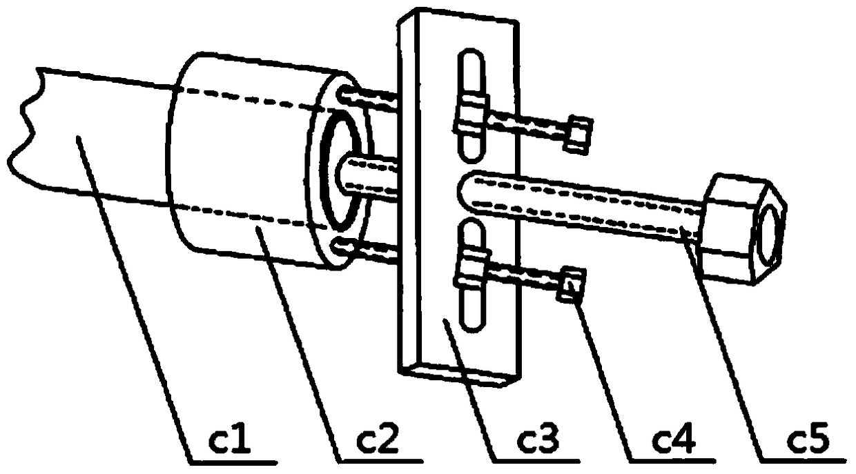
The invention relates to a spacer bush dismounting device and method. The spacer bush dismounting device is used for dismounting a spacer bush from a first part where the spacer bush is assembled, and comprises at least one first dismounting block. The first dismounting blocks are detachably mounted on the spacer bush and at least partially exposed out of the inner wall or the outer wall of the spacer bush to achieve relative movement of the spacer bush and the first part through external force applied on the exposed portions of the first dismounting blocks by means of a force applying part. According to the spacer bush dismounting device and method, the first dismounting blocks are detachably mounted on the spacer bush to achieve relative movement between the spacer bush and the first dismounting blocks through the force applied on the portions, exposed out of the spacer bush, of the first dismounting blocks by means of the force applying part, and therefore dismounting of the spacer bush is achieved; by adoption of the spacer bush dismounting device, the requirements for the wall thickness of the spacer bush are lowered, the structure is simple, the cost is low, dismounting is convenient, the time and labor are saved, the maintenance time can be shortened, and the maintenance efficiency of a whole vehicle is improved.

Description

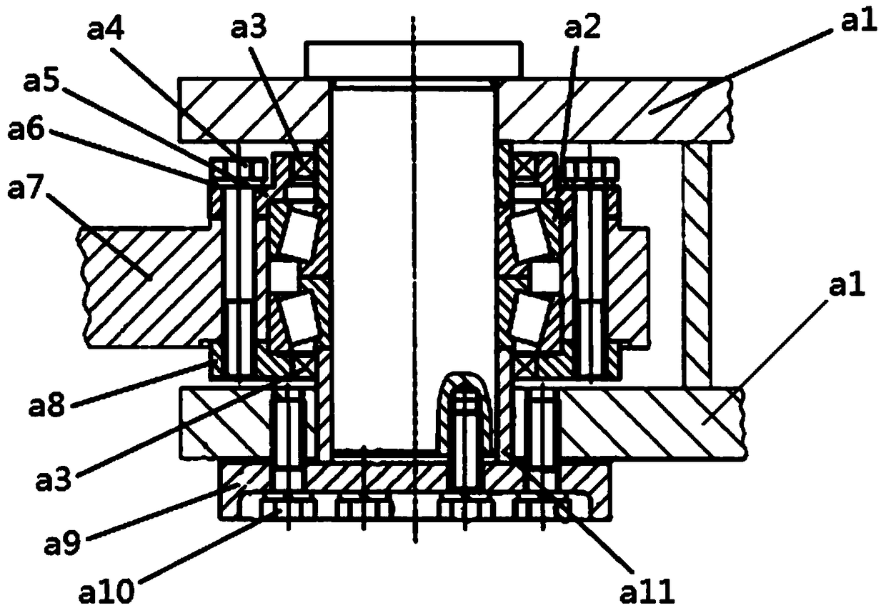
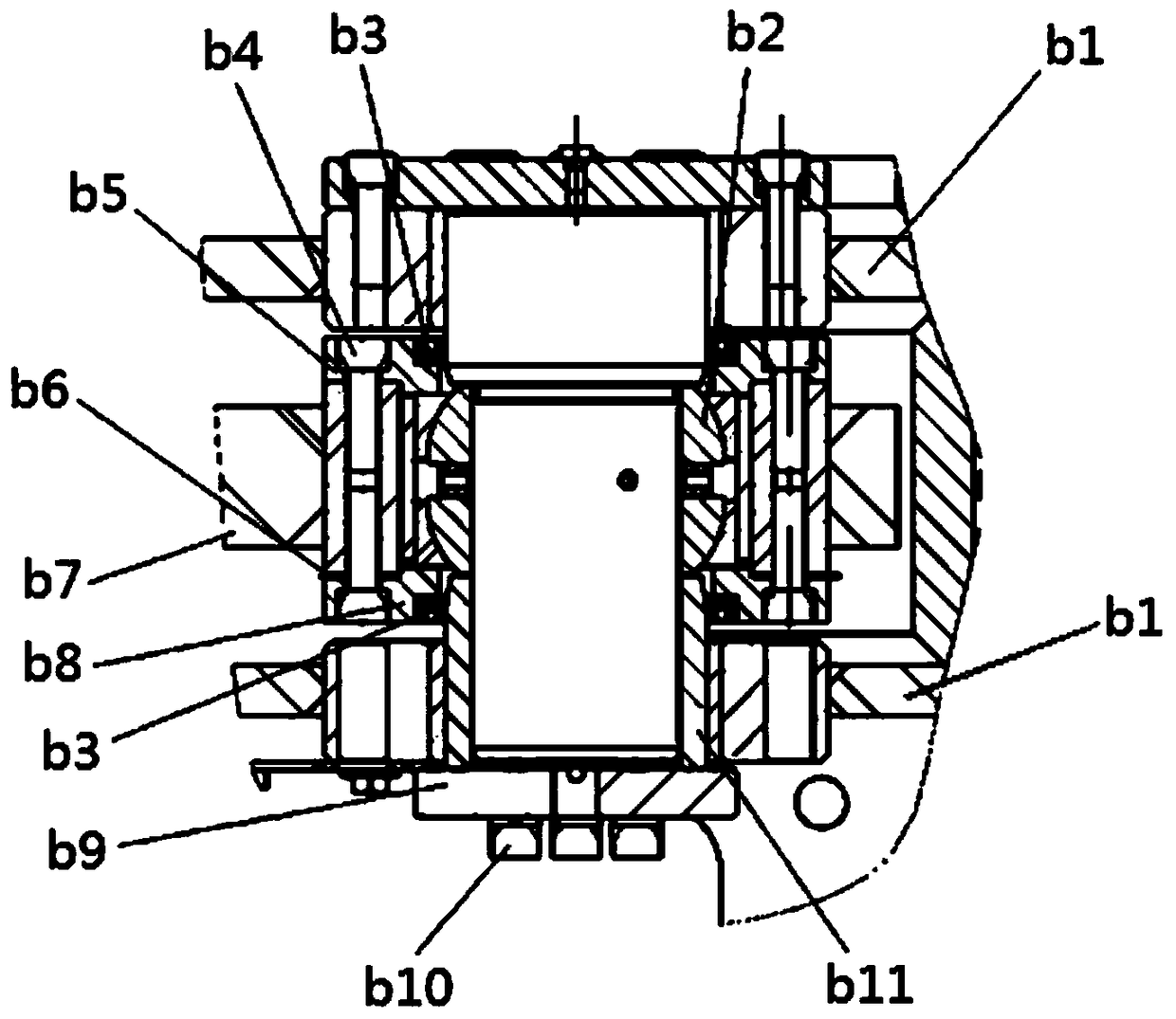
technical field [0001] The invention relates to the technical field of engineering machinery, in particular to a spacer sleeve removal device and a spacer sleeve removal method. Background technique [0002] An underground scraper is a wheeled vehicle used in underground mining operations (shoveling, transporting, unloading). At present, the frame central hinge device applied to loaders and underground scrapers generally consists of a central hinge pin, a bearing set on the central hinge pin, and a front frame hinge seat and a rear hinge connected to each other through the central hinge pin. Frame hinged seat composition. The structure can bear both radial force and axial force, the bearing wear can be adjusted within a certain range, the hinged connection of the front and rear frames can be kept in good condition, and the reliability of the equipment can be improved, so it is widely used. The axial fixation of the bearing inner ring of this central hinge device needs to r...

Claims


Application Information

Patent Timeline
Patent Type & Authority Patents(China)
IPC IPC(8): B25B27/06
CPCB25B27/06
Inventor 王川川孟祥伟蔡中义
Owner XCMG CONSTR MACHINERY
Learn More