Gun smart safety trigger lock

A trigger lock and gun technology, applied in the field of trigger locks, can solve the problems of user danger, complicated unlocking operation, and long time consumption, and achieve the effects of reasonable structure setting, convenient and quick unlocking, and high safety performance

Active Publication Date: 2018-05-11
FENGHUA JINFENG MACHINERY
View PDF5 Cites 0 Cited by
  • Summary
  • Abstract
  • Description
  • Claims
  • Application Information

AI Technical Summary

Problems solved by technology

[0003] In the prior art, the gun trigger lock generally uses a combination wheel or a key to control the lock lever to open the trigger lock. The unlocking operation is complicated and takes a long time. However, it is inconvenient to use when it needs to be used in an emergency. Thereby putting the user in a more dangerous situation, not only that, but the locking mechanism currently on the market generally adopts a bolt-type structure, but the bolt-type structure is relatively simple, and the safety protection effect is general, which affects the safety of the gun on the contrary, and the structure is easier to damage , making the user unable to use the firearm

Method used


Image

  • Gun smart safety trigger lock
  • Gun smart safety trigger lock
  • Gun smart safety trigger lock

Examples


Embodiment Construction

[0024] The present invention will be further described below in conjunction with the accompanying drawings.

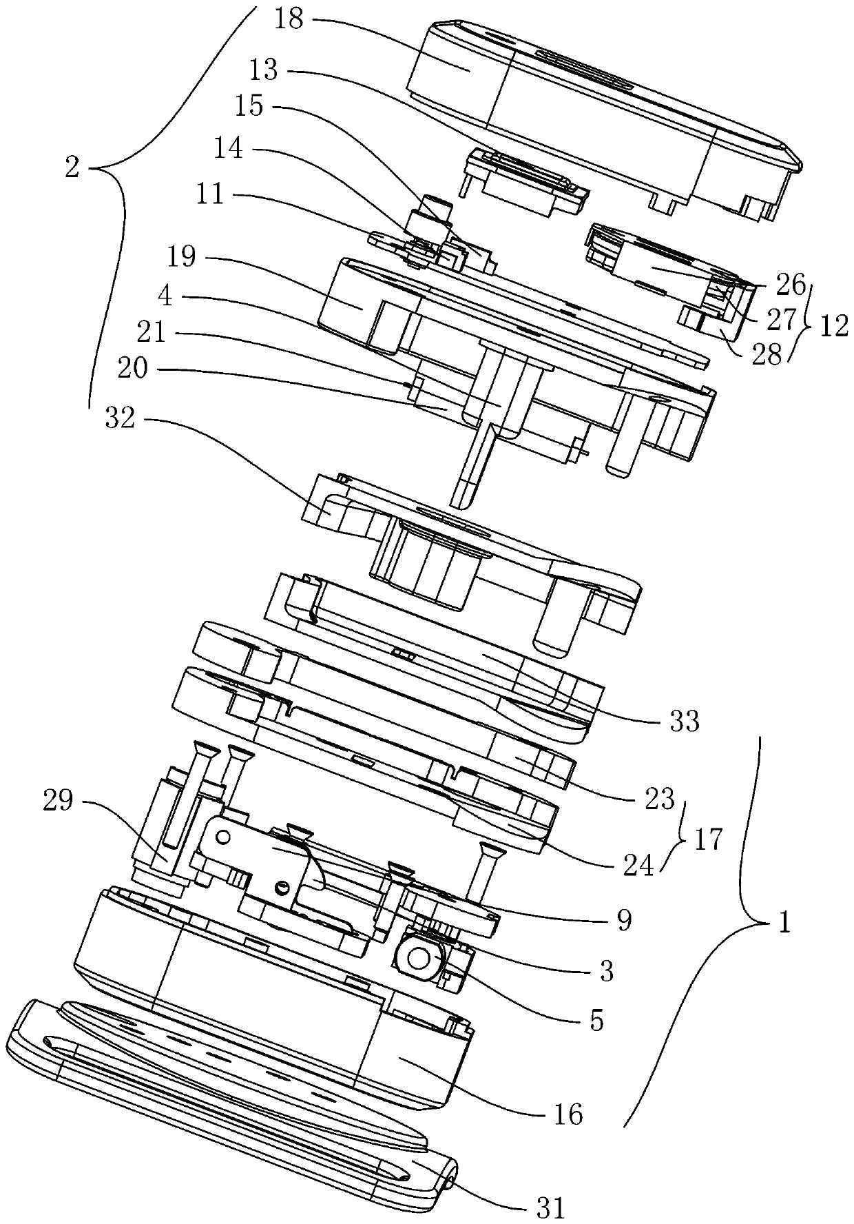
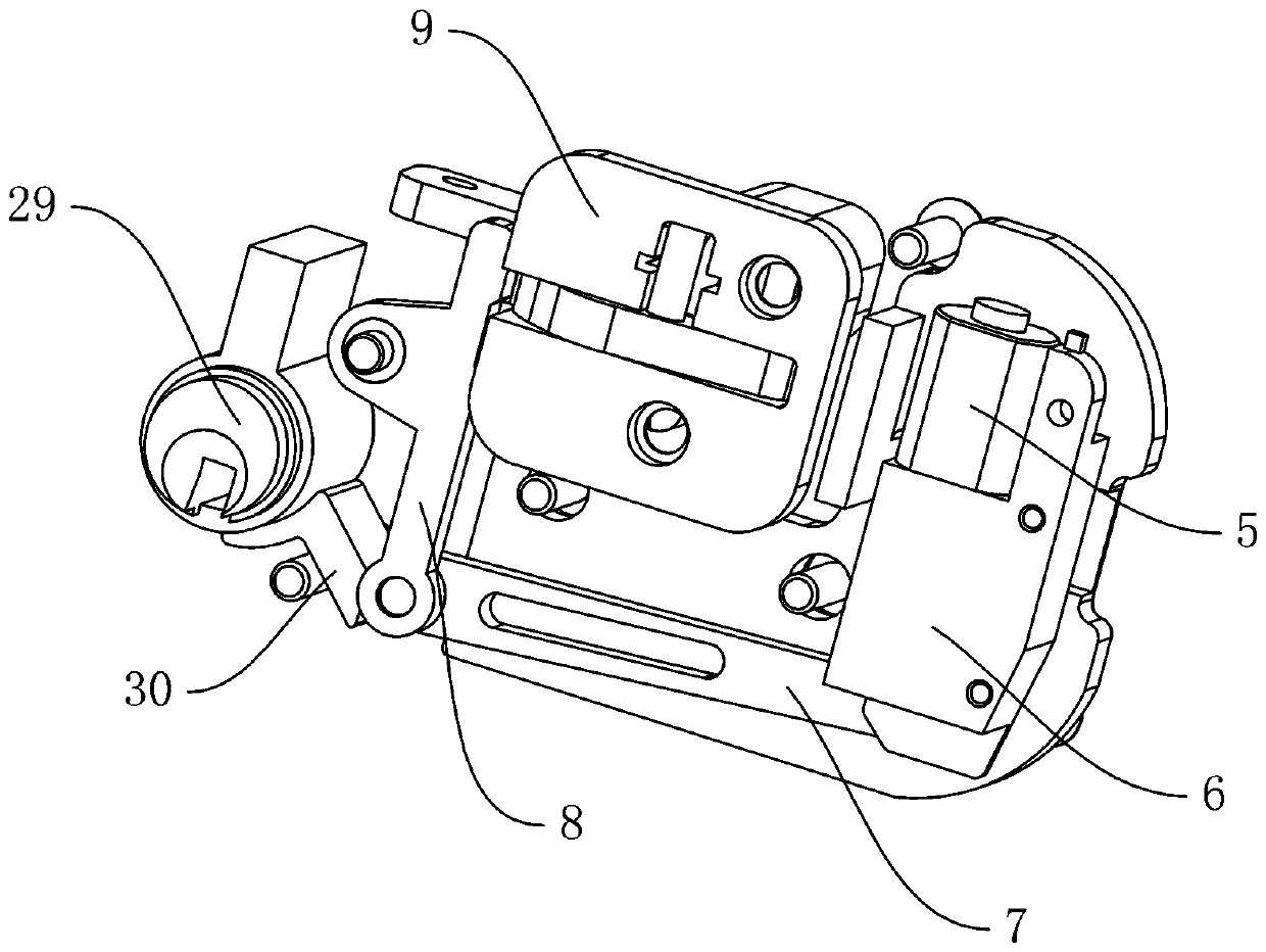
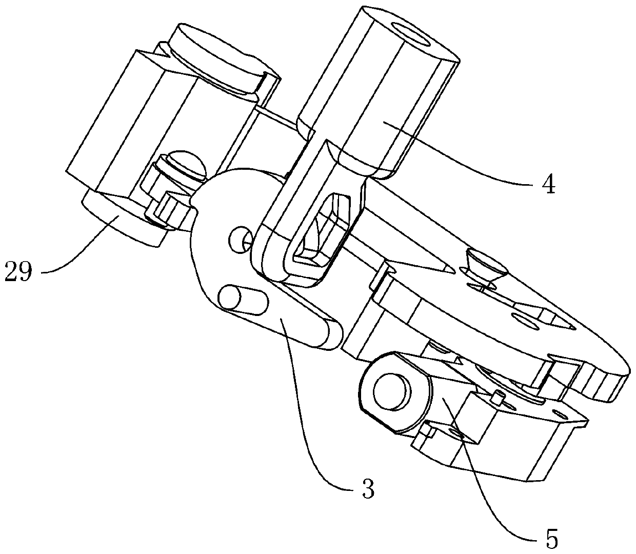
[0025] Such as Figure 1 to Figure 6 As shown, the gun intelligent safety trigger lock according to the present invention includes a left lock base 1 and a right lock base 2 which are interlocked with each other. After the left lock base 1 and the right lock base 2 are locked, they can be fixedly placed in the trigger position of the gun. , the left lock seat 1 is hinged with the side of the right lock seat 2, the left lock seat 1 includes a lock hook 3 and a locking mechanism that drives the lock hook 3 to operate, and the right lock seat 2 includes a lock catch 4 that cooperates with the lock hook 3 and controls the locking The main control module of the mechanism operation, the lock catch 4 is fixedly arranged on the side adjacent to the left lock base 1 of the right lock base 2; the locking mechanism includes a motor 5, a worm gear mechanism 6, a first Connecting ...


PUM


Abstract

The invention relates to an intelligent safety trigger lock for a gun. The intelligent safety trigger lock comprises a left lock seat and a right lock seat which are locked to each other. The side edge of the left lock seat and the side edge of the right lock seat are hinged. The left lock seat comprises a lock hook and a locking mechanism which drives the lock hook to act. The right lock seat comprises a lock catch and a master control module which controls the locking mechanism to act. The lock catch is fixedly arranged at one side of the right lock seat. The locking mechanism comprises a motor, a worm wheel and worm mechanism, a first connecting rod, a second connecting rod and a fixing plate, wherein the motor is arranged in the left lock seat. The middle of the second connecting rod is connected into the left lock seat in a pivoted manner. The lock catch is movably mounted onto the fixing plate through a torsional spring. A driving shaft of the motor is connected with the input end of the worm wheel and worm mechanism. The output end of the worm wheel and worm mechanism is hinged to a first end of the first connecting rod. A second end of the first connecting rod is hinged to a first end of the second connecting rod. A second end of the second connecting rod is in limited fit with the lock catch. The intelligent safety trigger lock is reasonable in structural arrangement; the connecting rod type torsional spring locking mechanism is controlled through the master control module; safety performance is improved; and unlocking can be conducted conveniently and rapidly.

Description

technical field [0001] The invention relates to the technical field of trigger locks, in particular to an intelligent safety trigger lock for guns. Background technique [0002] Guns are controlled weapons with serious lethality. They must be kept strictly and cannot be used by unauthorized persons. If the gun does not have a safety lock, the trigger may be misfired and misfired, or it may be used illegally by others, which will cause serious consequences. , The gun safety lock can lock the trigger part of the gun so that it cannot be used casually. It can only be used when the gun safety lock is unlocked, which can ensure the safety of the gun. [0003] In the prior art, the gun trigger lock generally uses a combination wheel or a key to control the lock lever to open the trigger lock. The unlocking operation is complicated and takes a long time. However, it is inconvenient to use when it needs to be used in an emergency. Thereby putting the user in a more dangerous situat...

Claims


Application Information

Patent Timeline
Patent Type & Authority Patents(China)
IPC IPC(8): F41A17/46E05B47/00E05B49/00
CPCE05B47/0012E05B49/00E05B2047/0058F41A17/46
Inventor 李峰许再宏竺开明
Owner FENGHUA JINFENG MACHINERY
Why Eureka
Try Eureka