Two-wheel bicycle lock

A technology of car lock and lock tongue, applied in the field of two-wheeled car locks, can solve the problems of improper operation of the lock bow and the like

Inactive Publication Date: 2007-03-07
ABUS AUGUST BREMICKER SOEHNE AG
View PDF0 Cites 21 Cited by
  • Summary
  • Abstract
  • Description
  • Claims
  • Application Information

AI Technical Summary

Problems solved by technology

[0003] Another two-wheeler lock that overcomes the above-mentioned problems has the disadvantage of being in a working state where the lock bow may not be properly operated, in which the transmission only drives the bolt and not the lock bow

Method used


Image

  • Two-wheel bicycle lock
  • Two-wheel bicycle lock
  • Two-wheel bicycle lock

Examples


Embodiment Construction

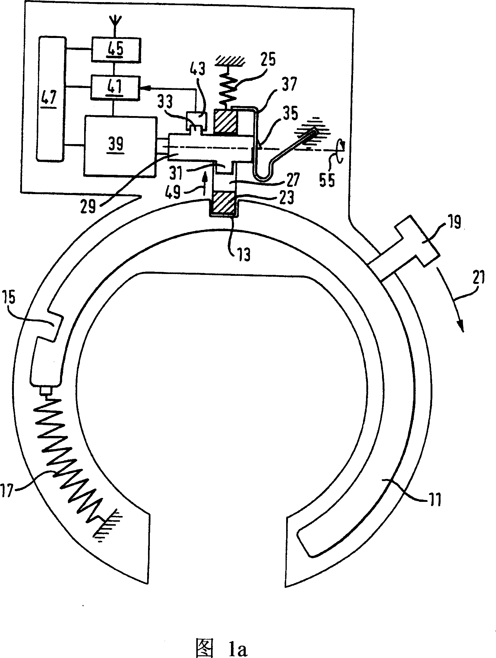
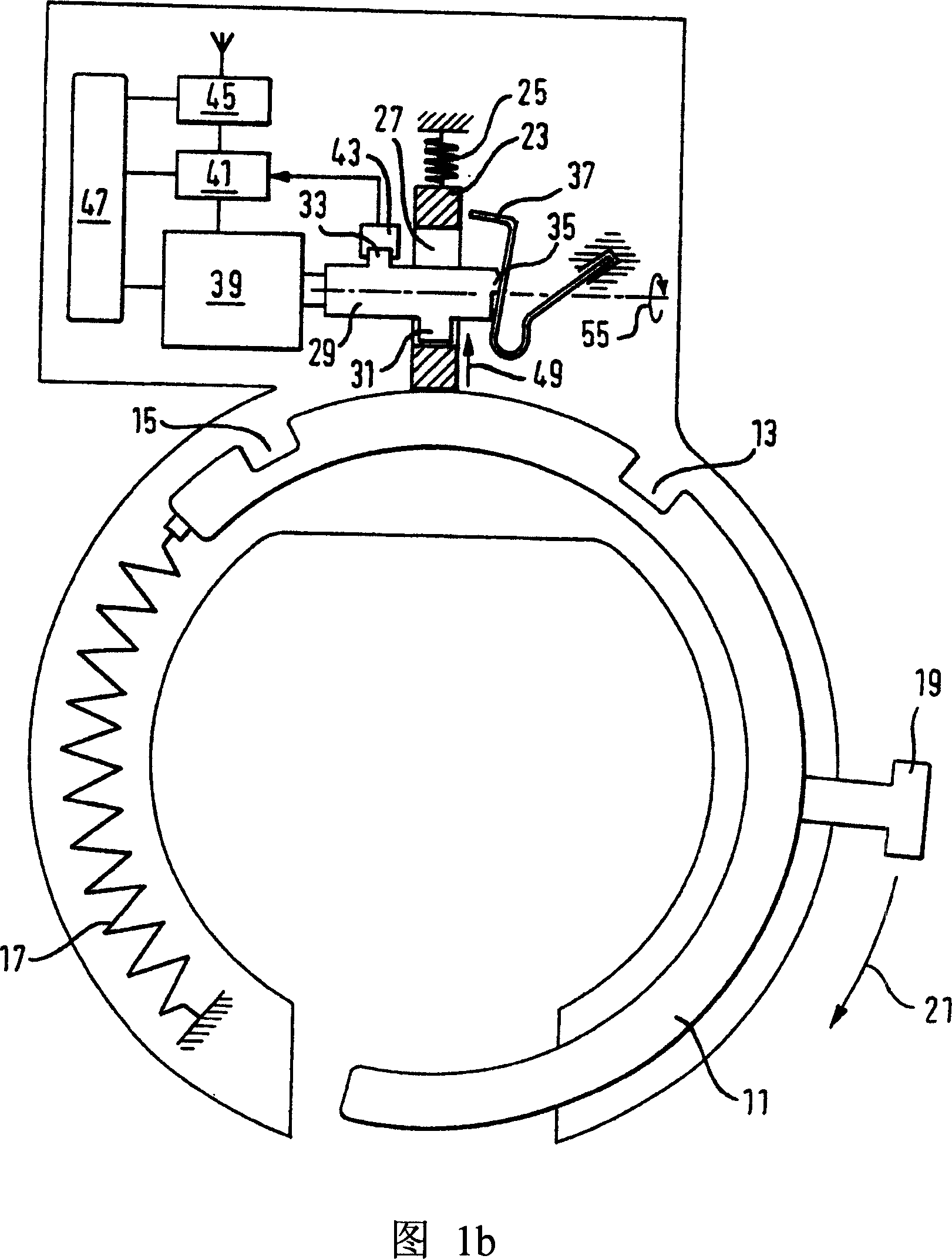
[0025] Fig. 1 schematically shows the structure of the frame lock installed on the rear wheel beam of the bicycle according to the present invention. The frame lock has a circular lock bow 11 to lock the rear wheel. The circular locking bow 11 has a first snap-in groove 13 and a second snap-in groove 15 and is biased by means of a tension spring 17 in the direction of the open position shown in FIG. 1 a. When the circular locking bow 11 is not bolted, it can be turned against the bias by means of the handle 19 in the locking direction 21 in the direction of the locked position.

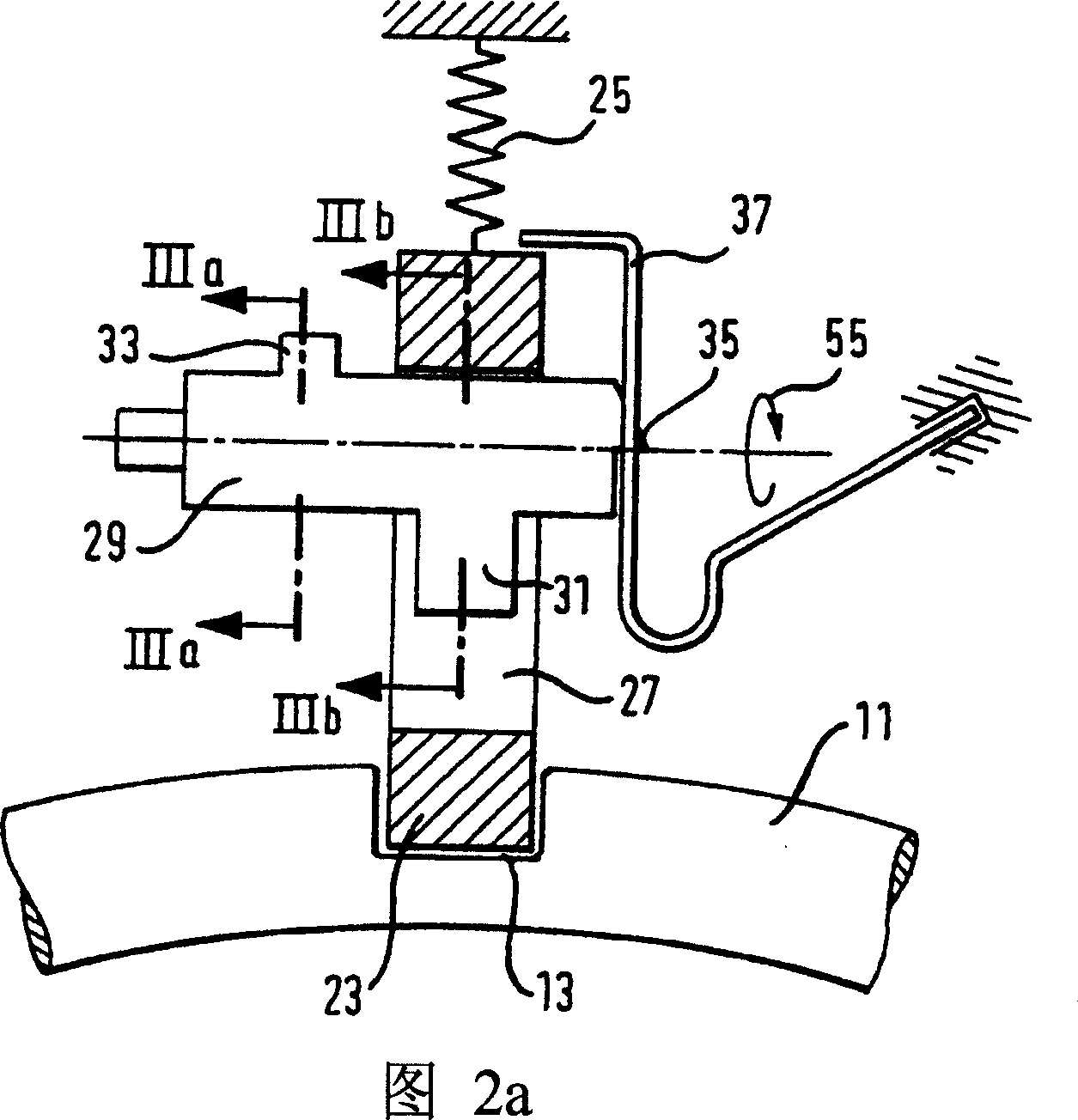
[0026] The locking tongue 23 cooperates with the circular locking bow 11 and is biased by a pressure spring 25 in the direction of the upper locking tongue position shown in FIG. 1a. The bolt 23 has a central recess 27 . The shaft 29 engages with the central recess 27 and has a bolt-release cam 31 in the area of ​​the bolt 23 (see FIG. 3 b and the cross-sectional view of FIG. 4 ). The shaft 29 has ...


PUM


Abstract

The present invention relates to a two-wheel bicycle lock, it is provided with a hoop, a bolt, a spring unit for pressing the bolt in the direction of the locked position, and a transmission device. In the said spring unit, said bolt locks the said hoop. The bolt can move to the unlocking position in a predetermined time span recur to the transmission device, and the bolt can move again in the direction of locking position automatically after a predetermined time span recur to the spring unit.

Description

technical field [0001] The invention relates to a two-wheeled vehicle lock with a bow, a bolt, a biasing device (Vorspanneinrichtung) for biasing the bolt in the direction of the upper bolt position, and a transmission, in which the bias In the pressing device, the lock bolt locks the lock bow. Background technique [0002] Such locks are used to lock two-wheeled vehicles against unauthorized use. Two-wheeled vehicle locks are known with an electric transmission of an upper bolt mechanism, wherein the transmission selectively actuates the locking bow into a locked position or an unlocked position. Since the locking bow of a two-wheeler lock generally has a relatively high mass, correspondingly large inertial forces, which have a negative effect on energy consumption, must be overcome in this case. Therefore, such two-wheeler locks are not suitable for applications with independent energy sources (batteries or accumulators). [0003] Another motorcycle lock in which the tr...

Claims


Application Information

Patent Timeline
Patent Type & Authority Applications(China)
IPC IPC(8): E05B71/00
CPCE05B2047/0093E05B67/28E05B47/0012B62H5/147E05B2047/0065E05B71/00E05B47/0603
Inventor 托马斯·贝克尔
Owner ABUS AUGUST BREMICKER SOEHNE AG
Why Eureka
Try Eureka