High-maneuverability building outer wall aerial working platform structure

A high-altitude work platform, building exterior wall technology, applied in building structure, building, housing structure support and other directions, can solve the problems of inconvenient transportation and placement, affecting operation efficiency, shaking of suspended platform, etc., to achieve convenient transportation and placement, The effect of enhancing support stability and enhancing adaptability

Active Publication Date: 2018-03-13
成都华阳建筑股份有限公司
View PDF7 Cites 21 Cited by
  • Summary
  • Abstract
  • Description
  • Claims
  • Application Information

AI Technical Summary

Problems solved by technology

[0004] In order to overcome the deficiencies of the prior art, the present invention proposes a high-mobility building outer wall aerial work platform structure, which solves the problem that the existing hanging basket is large in size, inconvenient to transport and place, and inconvenient to move during operation, which greatly affects At the same time, when the operator moves on the suspension platform, it will cause the suspension platform to shake, the stability is poor, and it is easy to cause safety hazards

Method used


Image

  • High-maneuverability building outer wall aerial working platform structure
  • High-maneuverability building outer wall aerial working platform structure
  • High-maneuverability building outer wall aerial working platform structure

Examples


Embodiment 1

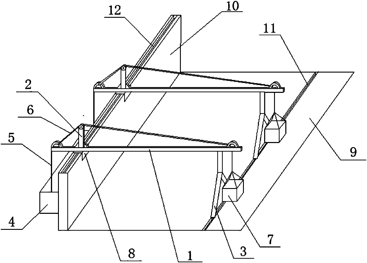
[0040] Such as figure 1 As shown, a high-mobility building exterior wall aerial work platform structure described in this embodiment includes a suspension platform and a suspension platform, the suspension platform includes a support frame, cables 6 and counterweights 7, and the support frame includes a beam 1, a mast 2 and the feet 3, one end of the beam 1 protrudes from the outer wall 10 and is fixed on the upper edge of the outer wall 10, the other end of the beam 1 is supported by the feet 3 on the roof surface 9, and the mast 2 is vertically arranged on the beam 1 , and the free end of the mast 2 extends vertically upwards, the two ends of the cable 6 are respectively fixed on the two ends of the beam 1, the mast 2 lifts up the cable 6 and makes the cable 6 in a tight state, and the counterweight 7 is suspended from the beam 1 down, and the counterweight 7 and the foot 3 are located at the same end of the beam 1.

[0041]In this embodiment, the cables 6 and the mast 2 ar...

Embodiment 2

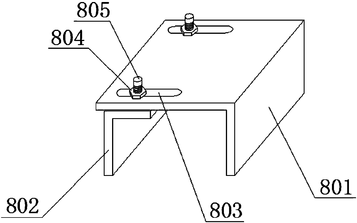
[0045] Such as figure 2 , image 3 , Figure 4 As shown, this embodiment is based on Embodiment 1, in order to further enhance the stability of the suspension platform, a clamp 8 is added, the clamp 8 is arranged under the beam 1, and the clamp 8 is clamped on the outer wall 10 .

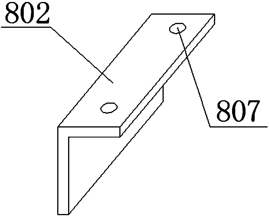
[0046] Specifically, the present embodiment realizes the function of the chuck through the following structure: the chuck 8 includes a static plate 801, a moving plate 802, a first nut 804 and a first bolt 805, and the static plate 801 and the moving plate 802 are respectively located on the outer wall 10 Both sides of the static plate 801 and the moving plate 802 are L-shaped plates. The static plate 801 and the moving plate 802 form a U-shaped structure with an opening downward. The U-shaped structure is just stuck on the outer wall 10. A bar-shaped hole 803 is provided, and a stepped hole 807 is provided on the moving plate 802. One section of the stepped hole 807 is circular, and the other se...

Embodiment 3

[0049] Such as Figure 6 As shown, this embodiment is basically the same as Embodiment 2, except that the beam 1 includes a moving rod 101 and a static rod 102, and the moving rod 101 is provided with at least one through hole 104, preferably two through holes 104, The static rod 102 is provided with several jacks 103 positioned on the same level as the through holes 104, and the jacks 103 are arranged in a row. When the length of the crossbeam 1 is adjusted and the through holes 104 coincide with any jack 103, then it can be inserted The bolt realizes the locking of the length of the beam 1, so that the appropriate beam length can be selected as much as possible according to the size of the floor, so that the hanging basket device has higher stability and safety. During installation, the length of the beam can be effectively reduced, which is convenient for the transportation and placement of the hanging basket device.

[0050] Such as Figure 7 , Figure 8 , Figure 9 As...


PUM


Abstract

The invention discloses a high-maneuverability building outer wall aerial working platform structure. The high-maneuverability building outer wall aerial working platform structure comprises a hangingplatform and a suspended hanging platform, and the hanging platform comprises supporting frames, a cable and a counterweight, wherein each supporting frame comprises a crossbeam, a mast and a supporting foot; one end of each crossbeam extends out of an outer wall and is fixed at the upper edge of the outer wall, and the other end of each crossbeam is supported by the corresponding supporting footsupported on the roof surface; each mast is vertically arranged on the corresponding crossbeam, the counterweight is suspended below the corresponding crossbeam, and the counterweight and the corresponding supporting foot are located at the same end of the corresponding crossbeam; the high-maneuverability building outer wall aerial working platform structure further comprises a first track and asecond track, wherein the first track is arranged on the roof surface, a roller is arranged on the lower portion of each supporting foot, and the rollers on the lower portions of the supporting feet are embedded in the first track; and the second track is arranged at the upper edge of the outer wall, a roller is arranged on the lower portion of each crossbeam, and the rollers on the lower portionsof the crossbeams are embedded in the second track. According to the high-maneuverability building outer wall aerial working platform structure, mobile maneuverability of a hanging basket device canbe enhanced, adhesion force of the hanging basket device is also enhanced at the same time, and then stability and safety of the hanging basket device are enhanced accordingly.

Description

technical field [0001] The invention belongs to the field of building construction and maintenance, and in particular relates to a high-altitude operation platform structure for high-mobility building exterior walls. Background technique [0002] The hanging basket is a construction machine for high-altitude operations in construction projects, and it is used for curtain wall installation and exterior wall cleaning. The hanging basket is a new type of high-altitude operation equipment that can replace traditional scaffolding, reduce labor intensity, improve work efficiency, and can be reused. The use of construction hanging baskets has gradually become a trend. Wall construction, curtain wall installation, thermal insulation construction, maintenance and cleaning of exterior walls and other elevated operations are widely recognized. Scaffolding can be avoided, and construction costs are reduced. Compared with traditional scaffolding, construction costs are greatly reduced. ...

Claims


Application Information

Patent Timeline
Patent Type & Authority Applications(China)
IPC IPC(8): E04G3/28E04G3/30E04G3/32E04G3/34E04G5/00E04G5/02E04G5/06E04G5/04
CPCE04G3/28E04G3/30E04G3/32E04G3/325E04G3/34E04G5/00E04G5/006E04G5/02E04G5/046E04G5/06E04G2003/283E04G2003/286
Inventor 杨佳志
Owner 成都华阳建筑股份有限公司
Why Eureka
Try Eureka