
Magnetic gear

A magnetic gear and magnetic adjustment technology, applied in the field of magnetic gear, can solve the problems of large magnetic gear structure, unreasonable layout, poor positioning effect, etc.

Active Publication Date: 2017-08-18
SHENZHEN HOR TECH CO LTD
View PDF3 Cites 7 Cited by
  • Summary
  • Abstract
  • Description
  • Claims
  • Application Information

AI Technical Summary

Problems solved by technology

[0003] The existing magnetic gear is composed of a motor, an inner rotor, an outer rotor, a brake assembly and a magnetic frame. The inner rotor and the brake assembly are directly positioned on the rotating shaft of the motor, and the positioning effect is poor. In addition, the brake assembly, the magnetic frame Unreasonable arrangement with the inner and outer rotors, resulting in a larger structure of the magnetic gear

Method used


Image

  • Magnetic gear
  • Magnetic gear
  • Magnetic gear

Examples


Embodiment Construction

[0026] The present invention will be further described below in conjunction with the accompanying drawings.

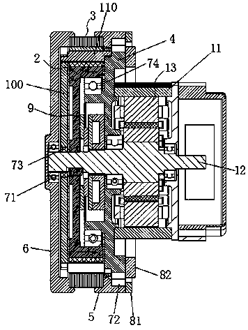
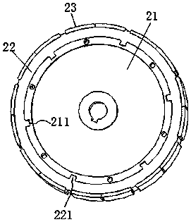
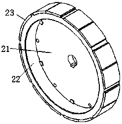
[0027] Such as figure 1 As shown, a magnetic gear of the present invention includes a motor casing 11, a motor rotor 12, a stator 13, an inner rotor 2 and an outer rotor 3, the stator 13 is arranged in the motor casing 11, and the motor rotor 12 is rotatably supported in the stator 13 , and one end of the motor rotor 12 extends outside the motor casing 11, the inner rotor 2 and the motor rotor 12 are keyed, the outer rotor 3 is placed outside the inner rotor 2 with the same axis, and the motor rotor 12 drives the inner rotor 2 to rotate, Under the action of magnetic field force, the inner rotor 2 drives the outer rotor 3 to rotate. The magnetic gear of the present invention also includes a front end cover 4, a rear bracket 5, a front bracket 6, a first bearing 71, a second bearing 72, a fourth bearing 74, a first pressure ring 81, a second pressure ring 82, a brake as...


PUM


Abstract

The invention discloses a magnetic gear. According to the invention, the front end cover is fixedly arranged on a motor housing. The internal rotor and the magnetism-adjusting support plate are connected to the front end cover and the motor rotor in a rotation manner through a fourth bearing and a third bearing respectively. The magnetism-adjusting support plate is connected with the front end cover through a magnetism-adjusting iron core. The back rack and the front rack are connected to the front end cover and the motor rotor in a rotation manner through a second bearing and a first bearing; and the front rack and the back rack are fixedly connected with the two end faces of the external rotor. The first press ring and the second press ring are fixedly arranged on the back rack and the front end cover respectively; and the second press ring and the first press ring abut against the inner ring and the outer ring of the second bearing respectively. The brake component is sleeved on the motor rotor and is located inside the internal rotor. The magnetic gear of the invention has a reasonably designed structure, and the support performances of the various components are good; the installation space for the various components is reduced; and therefore, the overall structure of the magnetic gear is reduced.

Description

technical field [0001] The invention relates to a magnetic gear. Background technique [0002] Magnetic gear is a new type of gear that uses magnetic force to transmit torque. In the process of magnetic gear transmission, there is no contact between the inner and outer rotors, no friction resistance, no wear, no noise, thus eliminating mechanical fatigue, friction loss and vibration noise, etc., and thus has been widely used. [0003] The existing magnetic gear is composed of a motor, an inner rotor, an outer rotor, a brake assembly and a magnetic frame. The inner rotor and the brake assembly are directly positioned on the rotating shaft of the motor, and the positioning effect is poor. In addition, the brake assembly, the magnetic frame The arrangement between the inner and outer rotors is unreasonable, resulting in a larger structure of the magnetic gear. [0004] Therefore, it is necessary to improve the prior art to solve the deficiencies of the prior art. Contents o...

Claims


Application Information

Patent Timeline
IPC IPC(8): H02K49/10H02K16/00
CPCH02K16/00H02K49/102
Inventor 李渊张天洪黄勇军张婷
Owner SHENZHEN HOR TECH CO LTD
Learn More