An electronic product aging test device

An aging test and electronic product technology, which is applied in the direction of measuring device, measuring electricity, measuring electrical variable, etc., can solve the problem that the aging test time and temperature control are prone to errors, the utilization rate of the aging test device is low, the site use of the aging test device, and the equipment Issues such as adverse effects of maintenance safety management

Active Publication Date: 2019-04-30
南通创硕电子科技有限公司
View PDF8 Cites 0 Cited by
  • Summary
  • Abstract
  • Description
  • Claims
  • Application Information

AI Technical Summary

Problems solved by technology

[0003] In the aging test device in the prior art, one aging test device can only carry out aging test for one product. Interface model requirements, so the utilization rate of the aging test device is low, and more types of aging test device have caused adverse effects on site use, equipment maintenance, safety management, etc., the existing aging test device when performing the aging test , technicians should always observe the progress of the aging test, they are prone to fatigue, and then errors are prone to occur in the time and temperature control of the aging test, which will affect the results of the aging test

Method used


Image

  • An electronic product aging test device
  • An electronic product aging test device
  • An electronic product aging test device

Examples


specific Embodiment approach

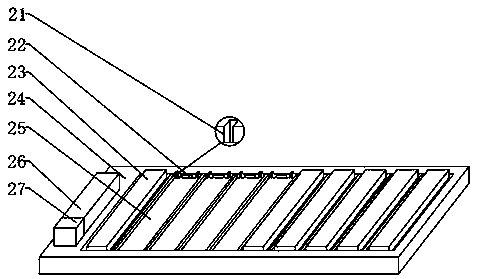
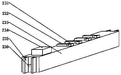
[0027]Specific embodiments: each detection interface 232 is connected in series with its corresponding indicator light 231 to form a small whole, and each small whole is connected together through a parallel circuit, and then connected with the variable resistor 234 through a series circuit, and the operator will The electronic components are connected to the detection interface 232, and the variable resistor 234 is adjusted to a suitable position to meet the voltage requirements of the electronic components. This design can ensure that each electronic component can independently carry out the aging test, and any problem with any electronic component can be repaired in time. It is found and does not affect other electronic components to continue to work.

[0028] The operator places the variable voltage detection board 23 on the upper end of the connection groove 25 through the fitting connection between the connection protrusion 235 and the positioning groove 21, the metal con...


PUM


Abstract

The invention provides an electronic product aging testing device which comprises the components of variable-voltage testing boards, a base, connecting troughs, a first timing switch controller, indicating lamps, testing interfaces, a supporting board and a rheostat. The ten connecting troughs are equidistantly arranged on the upper end of the base. The connecting troughs are connected through a parallel circuit. The upper end of each connecting trough is provided with a variable voltage testing board. The left side of the variable voltage testing board is provided with the first timing switch controller. The electronic product aging testing device realizes automatic switching-off of current applied to an electronic component; the testing interface are welded on the upper end of the supporting board; the testing interfaces are connected through the parallel circuit; the upper end of the supporting board is provided with the indicating lamps which are in one-to-one correspondence with the testing interfaces; and the upper end of the supporting board is provided with the rheostat. The electronic product aging testing device realizes suitability for aging tests of various electronic components with different voltages and interface types. The electronic product aging testing device has advantages of high convenience in use, high stability, high reliability, high functionality, wide application range, convenient mounting and convenient detachment.

Description

technical field [0001] The invention is an electronic product aging test device, which belongs to the field of product aging test devices. Background technique [0002] In the prior art, electronic products, whether they are components, components, complete machines, or equipment, must undergo aging and testing. Aging and testing are not a concept. First, aging and then testing, electronic products (all products are like this) through manufacturing Finally, a complete product is formed, which can already exert its use value, but after using it, it is found that there will be such and other problems, and it is found that most of these problems occur within a few hours to dozens of hours at the beginning, and then simply stipulated The aging and testing of electronic products, imitating or equivalent product use status, this process is completed by the product manufacturer. After re-testing, the problematic products are left in the factory, and the products without problems ar...

Claims


Application Information

Patent Timeline
Patent Type & Authority Patents(China)
IPC IPC(8): G01R31/00G01R1/02
CPCG01R1/02G01R31/00
Inventor 李朋国汤志强范珊珊
Owner 南通创硕电子科技有限公司
Why Eureka
Try Eureka