
Millimeter wave holographic imaging device with non-concentric relative cylindrical scanning

A holographic imaging and cylindrical scanning technology, applied in the field of radiation detection, can solve the problems of unsatisfactory imaging of inspection equipment, and achieve the effect of improving the automatic recognition rate, facilitating material identification, and comprehensive and accurate inspection

Active Publication Date: 2019-05-03
NUCTECH CO LTD +1
View PDF7 Cites 0 Cited by
  • Summary
  • Abstract
  • Description
  • Claims
  • Application Information

AI Technical Summary

Problems solved by technology

[0004] In view of the problem that the imaging of inspection equipment in the prior art is not ideal, the embodiment of the present invention provides a millimeter-wave holographic imaging equipment

Method used


Image

  • Millimeter wave holographic imaging device with non-concentric relative cylindrical scanning
  • Millimeter wave holographic imaging device with non-concentric relative cylindrical scanning
  • Millimeter wave holographic imaging device with non-concentric relative cylindrical scanning

Examples


Embodiment Construction

[0032] While the invention is susceptible to various modifications and alternative forms, specific embodiments thereof are shown by way of example in the drawings and will be described herein in detail. It should be understood, however, that the accompanying drawings and detailed description are not intended to limit the invention to the precise form disclosed, but on the contrary, are intended to cover within the spirit and scope of the invention as defined by the appended claims all modifications, equivalents and alternatives. The drawings are for illustration purposes and are not drawn to scale.

[0033] A number of embodiments according to the present invention will be described below with reference to the accompanying drawings.

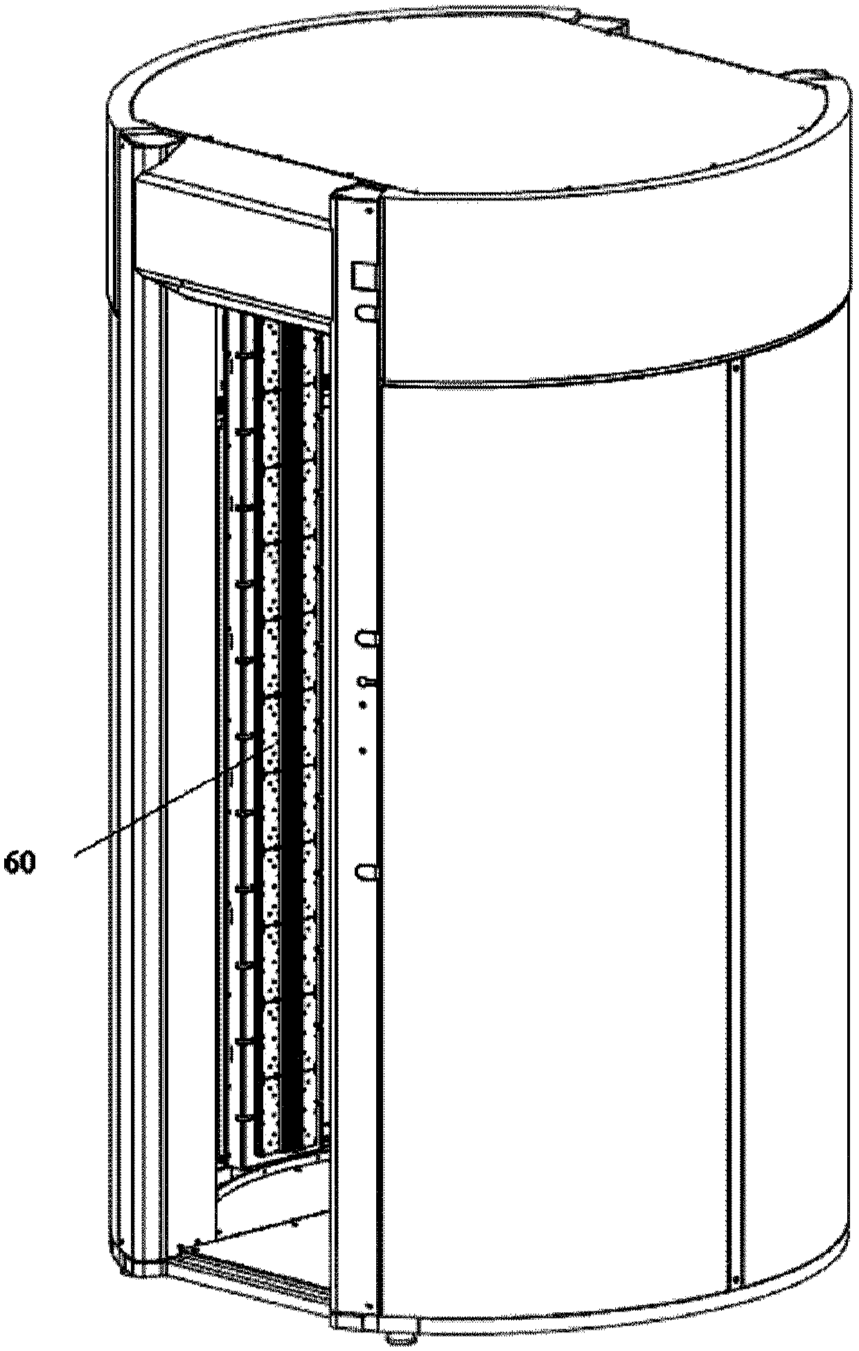
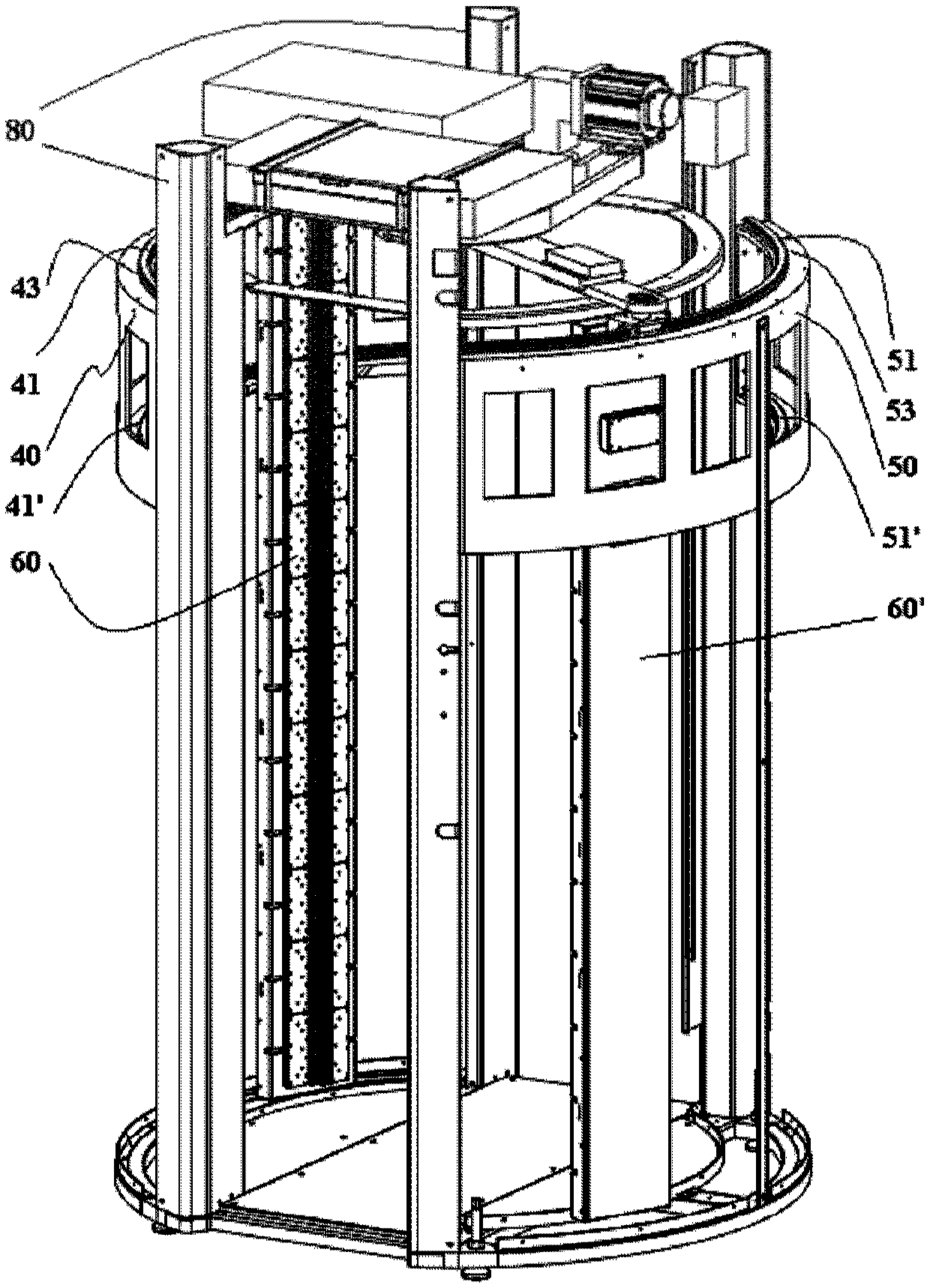
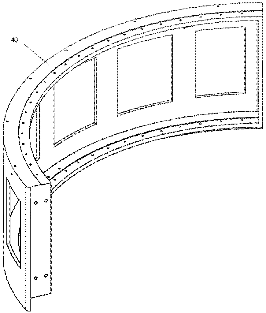
[0034] One embodiment of the present invention provides a millimeter-wave holographic imaging device capable of performing relative cylindrical scanning, such as figure 1 with 2 As shown, it includes: a first arc-shaped slide rail support 40 a...


PUM


Abstract

The invention discloses the millimeter wave holographic imaging equipment that can perform relative column scans. The millimeter wave holographic imaging equipment includes: the first and second arc -shaped slide -shaped sliding rail support; the top and the bottom of the first and second arc -shaped sliding rail branches The arc -shaped upper rails and arc -shaped lower rails of the arc -shaped slide with a limited arc -shaped trajectory are arranged. The limited arc -shaped trajectory constitutes a relatively non -concentric arc -shaped trajectory. First, the second vertical straight millimeter wave receiver device is arranged between the upper rail and the lower rail of the arc, and the arc -shaped slide rails that can follow the arc -shaped upper rail and the curved lower rail. First, the second vertical millimeter wave receiving device includes a millimeter wave income antenna array for sending and receiving millimeter wave signals. First, the second vertical millimeter wave sending device is separated from each other and relative settings to form a space for checking objects between the two. The rotary fork is also set to move the first and second vertical direct millimeter waves and sending device along the rounded skate rails, respectively.

Description

technical field [0001] The invention relates to the technical field of radiation detection, in particular to millimeter wave holographic imaging equipment. Background technique [0002] At present, the known millimeter-wave detection and imaging equipment adopts a cylindrical scanning method. The scanning trajectory of the cross section is circular, while the cross section of the human body is elliptical. Therefore, the scanning overlap is not high, resulting in The intensity consistency is poor, resulting in poor image imaging effect; the detector is hung vertically at a single point, the stability is poor, and the image shakes during movement, resulting in blurred images; in addition, the image imaging effect is poor, and the equipment adaptability is not good. [0003] It is desired to provide an inspection device with strong adaptability and improved imaging effect. Contents of the invention [0004] To solve the problem that the imaging of the inspection equipment in...

Claims


Application Information

Patent Timeline
Patent Type & Authority Patents(China)
IPC IPC(8): G01S13/89G01S7/02
CPCG01S7/02G01S13/89
Inventor 陈志强李元景吴万龙赵自然罗希雷金颖康郑志敏曹硕
Owner NUCTECH CO LTD
Learn More