Two-stage matrix converter-driven synchronous reluctance motor model prediction control method

A technology of synchronous reluctance motor and model predictive control, which is applied in the field of power electronics, can solve the problems of unstable output of two-stage matrix converter, large influence of PI regulator, and deterioration of input performance, so as to resist the influence of abnormal working conditions of the power grid , Eliminate the influence of parameter changes, and the effect of cheap rotor structure

Inactive Publication Date: 2017-05-10
XIAN UNIV OF TECH
View PDF5 Cites 7 Cited by
  • Summary
  • Abstract
  • Description
  • Claims
  • Application Information

AI Technical Summary

Problems solved by technology

[0004] With the development of society, the requirements for motor control performance are getting higher and higher in many occasions. In the traditional control system, the PI regulator has the disadvantages of being greatly affected by uncertain factors and complicated parameter setting, which has been difficult to meet the high-performance control requirements.
Due to the unique topology of the two-stage matrix converter, the lack of energy storage capacitors on the DC side brings advantages such as high power density of the device and also makes the two stages of rectification and inverter coupled to each other. Changes in the power grid and filter parameters on the input side will directly affect the Similarly, the performance of the power switch itself, the error of the detection device, and the influence of other factors such as the environment will directly lead to the instability of the output of the two-stage matrix converter. In this case, the two-stage matrix converter drives the synchronous reluctance motor. When the output performance will be affected, the input performance will also be degraded

Method used


Image

  • Two-stage matrix converter-driven synchronous reluctance motor model prediction control method
  • Two-stage matrix converter-driven synchronous reluctance motor model prediction control method
  • Two-stage matrix converter-driven synchronous reluctance motor model prediction control method

Examples


Embodiment Construction

[0070] The present invention will be described in detail below in conjunction with the accompanying drawings and specific embodiments.

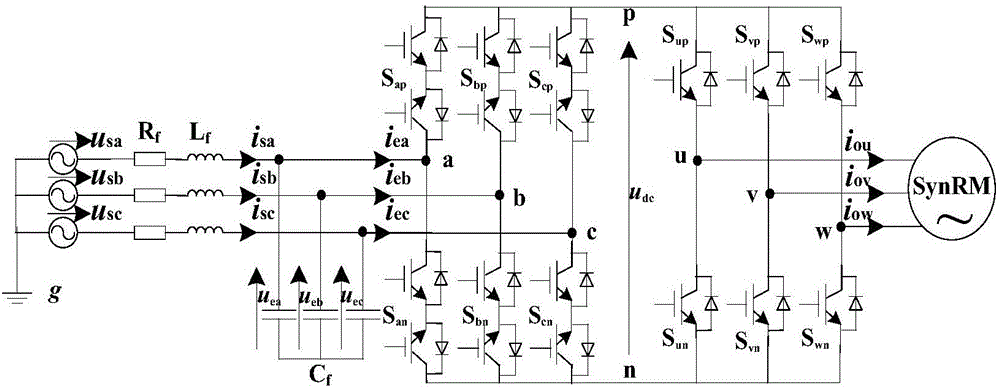
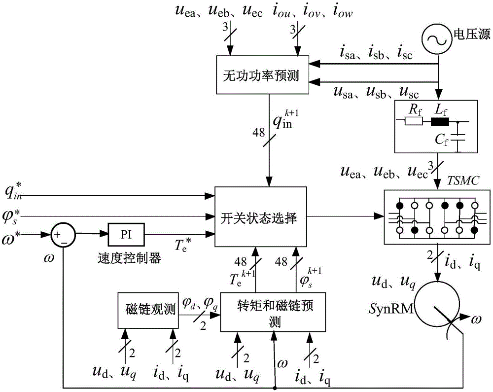
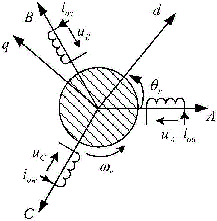
[0071] The synchronous reluctance motor model predictive control method driven by the two-stage matrix converter of the present invention utilizes the grid side input voltage ( figure 2 middle u sa , u sb , u sc ), current ( figure 2 middle i sa i sb i sc ), the input side voltage of the switching circuit ( figure 2 middle u ea , u eb , u ec ) and the switch matrix model of the two-stage matrix converter and the stator current of the synchronous reluctance motor ( figure 2 middle i ou i ov i ow ) and rotor angular velocity ( figure 2 In ω), the mathematical model of the synchronous reluctance motor system driven by the dual-stage matrix converter is established and discretized. According to the established discrete mathematical model, the input reactive power, the stator flux linkage and the electromagnetic torque of the sy...


PUM


Abstract

The invention discloses a two-stage matrix converter-driven synchronous reluctance motor model prediction control method. A mathematical model of a two-stage matrix converter-driven synchronous reluctance motor system is built based on the input voltage and current at the grid side, the voltage at the input side of a switching circuit, a two-stage matrix converter switching matrix model and the stator current and rotor angular velocity of a synchronous reluctance motor, and is discretized. The input reactive power, synchronous reluctance motor stator flux and electromagnetic torque are predicted according to the built discrete mathematical model. A performance function of error between the input reactive power, synchronous reluctance motor stator flux and electromagnetic torque at next moment and the reference values thereof is built, the switching state of the two-stage matrix converter is optimized with the performance function as a constraint, and the synchronous reluctance motor is controlled using the optimal switching state. The mutual coupling effect between the rectifier level and the inverter level can be eliminated, and the synchronous reluctance motor system driven by a two-stage matrix converter can have excellent transmission performance and high interference resistance.

Description

technical field [0001] The invention belongs to the technical field of power electronics, and in particular relates to a model predictive control method of a synchronous reluctance motor driven by a two-stage matrix converter. Background technique [0002] With the development of power electronics technology and computer control technology, AC speed control system has been gradually popularized, and its main power supply equipment is a power converter. Traditional power converters have been unable to overcome the inherent defects of the converter itself, such as low power factor, energy can only flow in one direction, and cause great pollution to the grid. In recent years, a new type of converter, the two-stage matrix converter, has been proposed. The topology is as follows: figure 1 As shown, there is no energy storage capacitor on the DC side, which reduces the size of the device while saving costs. In terms of performance, the input and output currents are sinusoidal, th...

Claims


Application Information

Patent Timeline
Patent Type & Authority Applications(China)
IPC IPC(8): H02P21/00H02P21/14H02P21/20H02P25/08
CPCH02P21/00H02P21/14H02P25/089
Inventor 宋卫章贾欢闫佳李敏远刘娜
Owner XIAN UNIV OF TECH
Why Eureka
Try Eureka