Lifting gantry structure

A technology on gantry and brackets, which is applied in the field of gantry structures, can solve problems such as high cost and inconvenient use, and achieve the effect of reducing production costs and improving application prospects

Active Publication Date: 2017-05-31
ANHUI RUIXIANG IND
View PDF7 Cites 4 Cited by
  • Summary
  • Abstract
  • Description
  • Claims
  • Application Information

AI Technical Summary

Problems solved by technology

[0002] In the prior art, due to the different welding positions of the car roofs of different models, the existing fixtures cannot meet the needs of multi-model roof welding, which is inconvenient to use and high in cost

Method used


Image

  • Lifting gantry structure
  • Lifting gantry structure
  • Lifting gantry structure

Examples


Embodiment Construction

[0023] The specific implementation manner of the present invention will be described in further detail below by describing the embodiments with reference to the accompanying drawings.

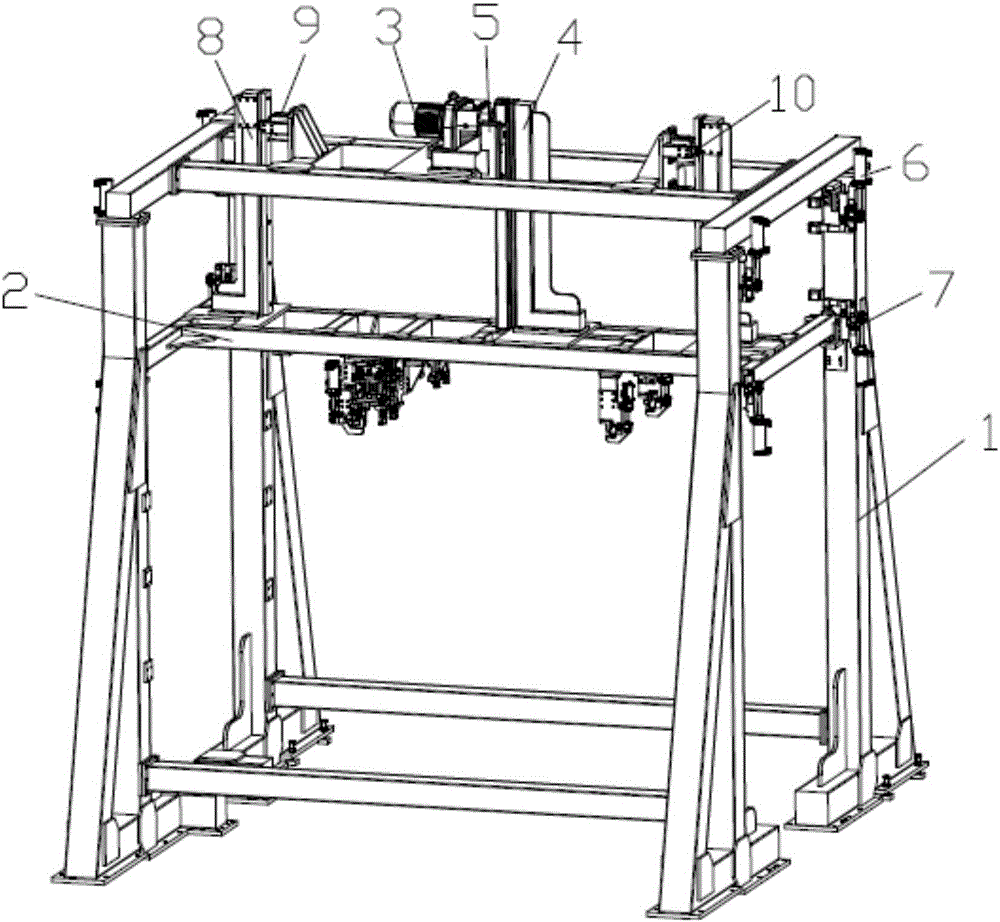
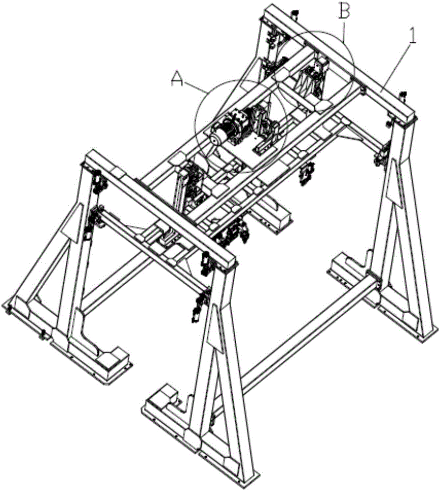
[0024] Lifting gantry structure of the present invention, as figure 1 , 2 As shown, including the support 1, the support 1 is provided with a drive mechanism that drives the moving seat 2 to move up and down, and the two sides of the drive mechanism are provided with a guide mechanism that controls the direction of movement, and the side of the support 1 is also provided with a fixed The upper locking mechanism 6 and the lower locking mechanism 7 of the mobile seat 2 positions. The moving seat 2 is used to clamp and position the roof of the car. The driving mechanism can drive the moving seat 2 to move up and down in the vertical direction. When it reaches the upper position, the upper locking mechanism 6 will lock the moving seat 2. , the mobile seat 2 is positioned and locked by the lower l...


PUM


Abstract

The invention discloses a lifting gantry structure. The lifting gantry structure comprises a bracket. A drive mechanism for driving a moving seat to move up and down is arranged on the bracket. Guide mechanisms for controlling the movement direction are arranged on the two sides of the drive mechanism. An upper locking mechanism and a lower locking mechanism which are used for fixing the position of the moving seat are arranged on the side edges of the bracket. By the adoption of the lifting gantry structure, the moving seat is stably and effectively driven by the drive mechanism to move up and down, positioning and welding of a top cover is precisely guaranteed, meanwhile the lifting gantry structure can meet the welding requirements of top covers of multiple models of vehicles due to the movable moving seat, collinear production is achieved, the production cost is lowered, and the lifting gantry structure has the good application prospects.

Description

technical field [0001] The invention belongs to the technical field of automobile assembly, and more specifically relates to a liftable gantry structure. Background technique [0002] In the prior art, because the welding positions of the roof covers of different models are different, the existing fixtures cannot meet the requirements for welding roof covers of multiple models, and are inconvenient to use and costly. Contents of the invention [0003] The purpose of the present invention is to solve the problems existing in the prior art, and provide a lifting gantry structure applicable to the welding of roof covers of multi-model automobiles, realizing multi-model collinear production and reducing production costs. [0004] In order to achieve the above object, the technical solution adopted by the present invention is: the lifting gantry structure provided is characterized in that it includes a bracket, and a driving mechanism for driving the moving seat to move up and ...

Claims


Application Information

Patent Timeline
Patent Type & Authority Applications(China)
IPC IPC(8): B23K37/04
CPCB23K37/0443
Inventor 吴守军程春霞
Owner ANHUI RUIXIANG IND
Why Eureka
Try Eureka