
a tray structure

A tray and tray seat technology, applied in the direction of rigid containers, containers, packaging, etc., can solve the problems of poor adaptability of automatic moving mechanism, affect the handling efficiency and quality of electronic components, and easily damage electronic components, so as to ensure the handling efficiency and Quality, Less Injury, Adaptable Effects

Active Publication Date: 2018-06-26
WUXI MINGZHU STEEL BALL
View PDF8 Cites 0 Cited by
  • Summary
  • Abstract
  • Description
  • Claims
  • Application Information

AI Technical Summary

Problems solved by technology

[0002] Electronic components are precision components, and the transportation and transfer in the production process require special pallets. The existing pallets are easy to damage the electronic components during the process of transportation and transfer of electronic components, and the existing pallet devices are also automatically moved with the electronic components. The adaptability of the mechanism is poor, which affects the efficiency and quality of electronic component handling

Method used


Image

  • a tray structure
  • a tray structure
  • a tray structure

Examples


Embodiment Construction

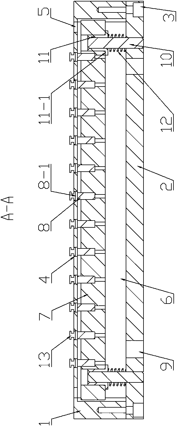
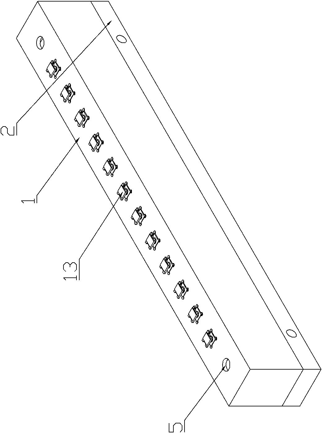
[0013] Such as Figure 1-Figure 3 As shown, a pallet structure includes a pallet base 1 and a bottom plate 2. The pallet base 1 is installed on the bottom plate 2 through screws 3. There are 12 workpiece placement slots 4 uniformly opened in the middle of the top of the pallet base 1, and the two sides of the top are symmetrical. The limited hole 5 is set, the tray seat 1 and the bottom plate 2 form a cavity 6, and a movable seat plate 7 is arranged in the cavity 6, and 12 tray columns 8 are evenly distributed on the movable seat plate 7, and the 12 tray columns 8 are respectively Embedded in the movable seat plate 7, the 12 tray columns 8 are compatible with the 12 workpiece placement slots 4 and can slide in the workpiece placement slots 4. The bottom of the tray seat 1 is symmetrically provided with positioning holes 9, and the movable seat plate 7 The two sides are respectively connected to the bottom plate 2 by pins 10, the bushing 11 is sleeved on the pins 10, the bottom...


PUM


Abstract

The invention provides a tray structure. The structure is high in adaptability to an automatic carrying mechanism for electronic components, so that the electronic components are not damaged easily during transfer, and the carrying efficiency and quality are guaranteed. The structure is characterized by comprising a tray seat and a bottom plate; the tray seat is mounted on the bottom plate; workpiece accommodating slots are evenly formed in the middle of the top of the tray seat; limiting holes are symmetrically formed in two sides of the top of the tray seat; a cavity is defined by the tray seat and the bottom plate; a moving seat plate is arranged in the cavity; tray columns are evenly distributed on the moving seat plate; heads of the tray columns adapt to the workpiece accommodating slots and are in sliding fit with the workpiece accommodating slots; and positioning holes are symmetrically formed in the bottom of the tray seat.

Description

technical field [0001] The invention relates to the technical field of electronic component manufacturing, in particular to a tray structure. Background technique [0002] Electronic components are precision components, and the transportation and transfer in the production process require special pallets. The existing pallets are easy to damage the electronic components during the process of transportation and transfer of electronic components, and the existing pallet devices are also automatically moved with the electronic components. The adaptability of the mechanism is poor, thereby affecting the handling efficiency and quality of electronic components. Contents of the invention [0003] In order to solve the problems in the prior art, the present invention provides a tray structure, which has strong adaptability to the automatic electronic component transport mechanism, makes the electronic components less likely to be damaged during transport and transfer, and ensures...

Claims


Application Information

Patent Timeline
Patent Type & Authority Patents(China)
IPC IPC(8): B65D19/26B65D19/38
CPCB65D19/0079B65D19/38B65D2519/00293B65D2519/00572B65D2519/00815
Inventor 吴昊
Owner WUXI MINGZHU STEEL BALL
Learn More