Supercharge Your Innovation With Domain-Expert AI Agents!

The elastic adjustment mechanism of the furniture sliding door

An adjustment mechanism and a technology for sliding doors, which are used in door/window fittings, building structures, and suspension devices for wing sashes. Assembly and other problems, to achieve the effect of improving the sliding opening and closing effect, improving the sliding opening and closing effect, and eliminating installation difficulties

Active Publication Date: 2018-05-11
伍志勇
View PDF6 Cites 0 Cited by
  • Summary
  • Abstract
  • Description
  • Claims
  • Application Information

AI Technical Summary

Problems solved by technology

It is said that this structure can automatically adjust the state of tight fit between the double guide wheels and the guide rails; however, it cannot adjust the upper and lower positions between the door body and the guide wheels, which is not conducive to the assembly of the door body, and the door body is unobstructed when it is closed. Negative effect, resulting in loud noise when the door is closed, which cannot meet the needs of users

Method used


Image

  • The elastic adjustment mechanism of the furniture sliding door
  • The elastic adjustment mechanism of the furniture sliding door
  • The elastic adjustment mechanism of the furniture sliding door

Examples


no. 1 example

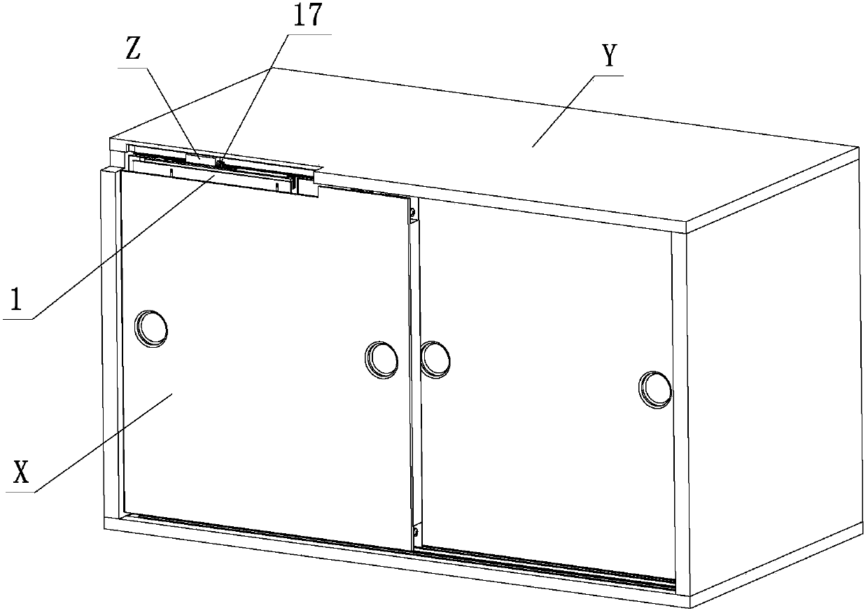
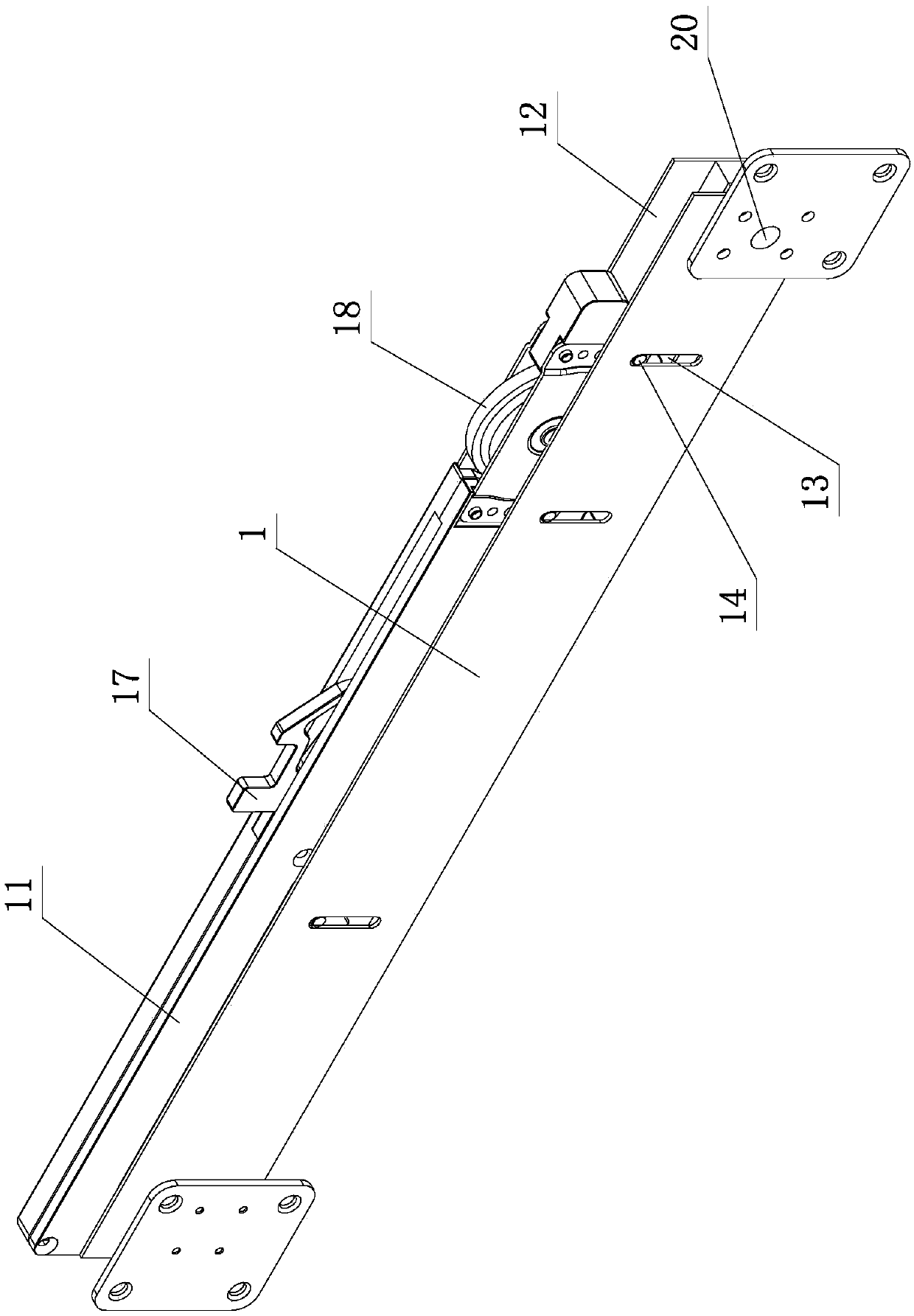
[0024] see Figure 1-Figure 6 , the elastic adjustment mechanism of the sliding door of this furniture includes a bracket element 1, a pushing element 2, an adjusting element 3, a damping assembly and a rotating wheel assembly, and the pushing element 2, the adjusting element 3, the damping assembly and the rotating wheel assembly are respectively movably arranged on the bracket element 1, the bracket element 1 is provided with a spring 4, one end of the spring 4 elastically acts on the damping assembly and / or the rotating wheel assembly, and the other end elastically acts on the bracket element 1, and the damping assembly and / or the rotating wheel assembly are elastic through the spring 4 The limit slides on the support element 1; the push element 2 is provided with an inclined part 5, the damping assembly and / or the rotating wheel assembly is provided with an inclined fitting part 6, the adjustment element 3 is positioned and rotated on the support element 1, and is connected...

no. 2 example

[0034] see Figure 7-Figure 9 , the elastic adjustment mechanism of the furniture sliding door is different from the first embodiment in that: the support element 1 is provided with a rotating element 21, and the rotating element 21 is provided with a positioning rotating part 22, a tooth matching part 23 and a rotating action part 24. The rotating element 21 is positioned and rotated on the support element 1 through the positioning rotating part 22, and is meshed and linked with the tooth part 7 of the adjusting element 3 through the tooth fitting part 23; wherein, the rotating element 21 is positioned and rotated on the support element 1 in the axis direction The axis direction of the positioning and rotation of the adjustment element 3 on the bracket element 1 is perpendicular to each other; through the tool or manual action to rotate the action part 24, the rotation element 21 is positioned and rotated on the bracket element 1 through the positioning rotation part 22, and t...


PUM


Abstract

An elastic adjusting mechanism for sliding doors of furniture comprises support elements, push elements, adjusting elements, damping components and rotating wheel components; the push elements, the adjusting elements, the damping components and the rotating wheel components are movably arranged on the support elements respectively; springs are arranged on the support elements; the damping components and / or the rotating wheel components slide on the support elements in an elastically limited manner through the springs; inclined parts are arranged on the push elements; inclined matching parts are arranged on the damping components and / or the rotating wheel components; the adjusting elements rotate on the support elements in a positioned manner and are linked with the push elements; tooth parts are arranged on the adjusting elements; and the tooth parts are affected by a tool or manually, the adjusting elements rotate in the positioned manner, and the push elements are driven to move and limit the sliding travel of the damping components and / or the rotating wheel components on the support elements during movement, so that the elastic sliding positions of the damping components and / or the rotating wheel components relative to the support elements are adjusted. Through improvement of the structure, the mechanism is high in practicability.

Description

technical field [0001] The invention relates to an elastic adjustment mechanism for a furniture sliding door. Background technique [0002] The Chinese patent literature number is CN204238725U, which discloses a sliding door guide wheel device on April 1, 2015, which includes a base plate, a support plate, a spring, a bolt, a first guide wheel, a second guide wheel, and a limit pin. The first guide wheel and the second guide wheel are arranged side by side on the support plate; the support plate is provided with a through hole, the base plate is provided with a threaded hole, and one end of the spring outer ring is fixed on the right end of the base plate; the nut end of the bolt is fixed to the support plate. The threaded end passes through the through hole and the inner ring of the spring to be threaded with the threaded hole in turn, and one end of the inner ring of the spring is located between the bolt and the right end of the bottom plate, and is in contact with the bo...

Claims


Application Information

Patent Timeline
Patent Type & Authority Patents(China)
IPC IPC(8): E05F5/02E05D15/06E05F5/04
CPCE05D15/0634E05F5/02E05F5/04E05F2005/046E05Y2900/20
Inventor 伍志勇
Owner 伍志勇
Features
  • R&D
  • Intellectual Property
  • Life Sciences
  • Materials
  • Tech Scout
  • Unparalleled Data Quality
  • Higher Quality Content
  • 60% Fewer Hallucinations
Learn More