A mechanical choke fishing tool and its operating method

A salvage tool and choke technology, applied in the field of mechanical choke salvage tools, can solve the problems of high cost and low salvage success rate, and achieve simple structure, easy inspection of tool conditions, low-cost salvage technology and economy. desired effect

Active Publication Date: 2019-04-09
PETROCHINA CO LTD
View PDF8 Cites 0 Cited by
  • Summary
  • Abstract
  • Description
  • Claims
  • Application Information

AI Technical Summary

Problems solved by technology

[0004] The purpose of the invention is to overcome the problems of high cost and low success rate of salvage in the prior art

Method used


Image

  • A mechanical choke fishing tool and its operating method
  • A mechanical choke fishing tool and its operating method
  • A mechanical choke fishing tool and its operating method

Examples


Embodiment 1

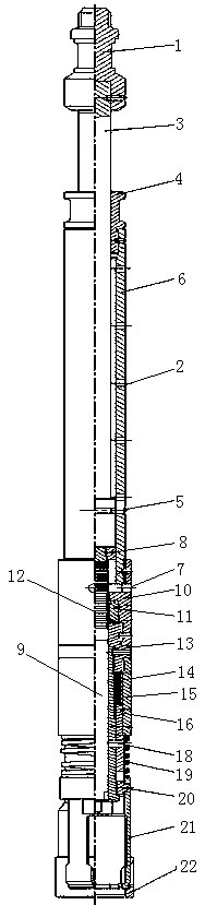
[0036] In order to overcome the problems of high cost and low success rate of salvage in the prior art, this embodiment provides a method such as figure 1 As shown in the mechanical throttle fishing tool, the upper end of the fishing mechanism is sequentially connected with a control rod mechanism and a shock rod mechanism, and the shock rod mechanism includes a shock rod 3 and an outer cylinder 6, and the shock rod 3 The upper end is connected to the upper joint 1, the outer side of the shock rod 3 is covered with a nut 4, the bottom end of the shock rod 3 is provided with a boss outside, the shock rod 3 is placed in the outer cylinder 6, and the nut 4 is connected to the inner side of the upper end of the outer cylinder 6, The lower end of the inner cylinder 6 is inserted with a shear pin 5, and the shear pin 5 is located below the shock rod 3. The control rod mechanism includes a control rod 9, a fixed sleeve 10 and a connecting seat 13. The upper end of the fixed sleeve 10 ...

Embodiment 2

[0044] On the basis of embodiment 1, this embodiment provides a kind of figure 1 In the fishing tool with mechanical restrictor shown, in order to prevent the tool from holding pressure during operation, the side wall of the outer cylinder 6 is provided with a vent hole 2 .

[0045] Further, the fixing sleeve 10 is provided with an observation hole 7 , and when the shear pin 5 is not cut, the observation hole 7 is aligned with the threaded lower end of the control rod 9 . The downward movement position of the control rod can be observed from the observation hole 7, which is convenient for checking the condition of the tool. At the same time, the observation hole 7 also has the effect of ventilation, so as to ensure that the fishing process is carried out normally.

Embodiment 3

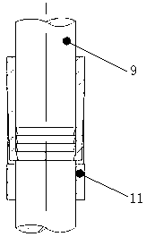
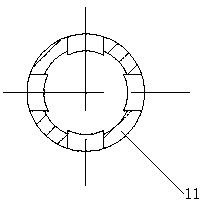
[0047] On the basis of embodiment 2, this embodiment provides a kind of figure 1 In the mechanical throttle fishing tool shown, a spacer sleeve 11 is embedded between the limit step of the fixed sleeve 10 and the connecting seat 13, the spacer sleeve 11 is internally connected to the circlip 12, and the control rod 9 is placed In the jump ring 12, and the top of the control rod 9 is provided with threads;

[0048] Alternatively, telescopic steps are provided on the inner wall of the spacer sleeve 11 , and an inverted tapered thread is provided above the control rod 9 .

[0049] When the restrictor is unsealed, the nut 8 and the control rod 9 are moved downward by the impact of the shock rod 3, and the thread on the control rod 9 is stuck in the retaining spring 12. When the shock rod 3 goes up, the control rod 9 cannot go up. , or the inverted tapered thread on the top of the control rod 9 is stuck on the telescopic step on the inner wall of the spacer sleeve 11. When the sho...


PUM


Abstract

The invention discloses a mechanical flow controller fishing tool and an operation method thereof. The mechanical flow controller fishing tool comprises a fishing mechanism. A control rod mechanism and a jar stem mechanism are sequentially connected to the upper end of the fishing mechanism. The jar stem mechanism comprises a jar stem and an outer cylinder. An upper joint is connected to the upper end of the jar stem. The jar stem is sleeved with a nut. A boss is arranged on the outer side of the bottom end of the jar stem. The jar stem is arranged inside the outer cylinder. The nut is connected with the inner side of the upper end of the outer cylinder. A shear pin is inserted into the lower end of the inner cylinder. The shear pin is located below the jar stem. The control rod mechanism comprises a control rod, a fixing sleeve and a connecting base. The upper end of the fixing sleeve is connected to the outer side of the lower end of the inner cylinder. The lower end of the fixing sleeve is connected with the connecting base. A limiting step is arranged on the inner side of the fixing sleeve. The control rod is arranged into an annulus formed by the fixing sleeve and the connecting base. The top end of the control rod is connected with the nut. The nut is arranged inside the outer cylinder. The problem that an existing downhole flow controller is not high in fishing success rate is solved, and the requirement for safety, reliability and low cost in gas field downhole flow controller fishing can be met.

Description

technical field [0001] The invention relates to downhole operation tools, in particular to a mechanical choke fishing tool and an operating method thereof. Background technique [0002] At present, downhole throttling technology has become one of the key technologies in the development of low pressure and low production gas fields. It is widely used in the initial stage of gas well production and has an important function of low pressure collection. It can reduce the surface distribution cost of low-pressure and low-yield gas wells in the early stage of development by several million yuan, and is an important means for the economical and effective development of low-pressure, low-yield gas fields. Therefore, it is widely used in the initial stage of low pressure and low production gas field development. [0003] However, due to downhole sand production, scaling, corrosion and other reasons, some wells have the problems of high difficulty and low success rate in salvaging do...

Claims


Application Information

Patent Timeline
Patent Type & Authority Patents(China)
IPC IPC(8): E21B31/18
CPCE21B31/18
Inventor 张安康王效明赵鹏玉白小佩王治国王尚卫胡相君刘江波王昌龄李旭梅张雄涛梁万银
Owner PETROCHINA CO LTD
Why Eureka
Try Eureka