Underground throttle fishing tool and operation method thereof

A technology for fishing tools and chokes, which is applied in the field of downhole choke fishing tools and fishing, can solve the problems of low success rate and high cost, and achieve the effects of high success rate, simple structure, low-cost technology and economical requirements

Pending Publication Date: 2018-02-09
PETROCHINA CO LTD
View PDF0 Cites 0 Cited by
  • Summary
  • Abstract
  • Description
  • Claims
  • Application Information

AI Technical Summary

Problems solved by technology

[0004] The purpose of the present invention is to overcome the problems o

Method used


Image

  • Underground throttle fishing tool and operation method thereof

Examples


Example Embodiment

[0026] Example 1:

[0027] This embodiment provides a method such as figure 1 The downhole choke fishing tool shown includes a pressure control mechanism and a fishing mechanism connected up and down.

[0028] Connect the pressure control mechanism and the fishing mechanism to form a fishing tool. After the fishing tool is lowered to the top of the throttle through the well test wire, the fishing tool is quickly lowered, and then the fishing tool is slowly raised. When the lifting force is greater than the hanging weight, the fishing tool After grabbing the fishing neck of the throttle, unblock the throttle, and lift up the fishing tool to lift the throttle.

Example Embodiment

[0029] Example 2:

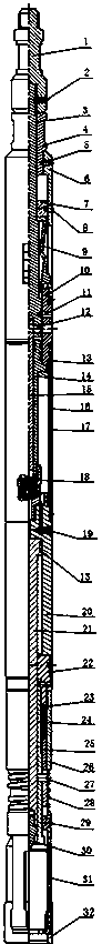
[0030] On the basis of Example 1, such as figure 1 As shown, the pressure control mechanism includes an upper joint 1, the inner wall of the lower end of the upper joint 1 is connected to the shock rod 3 through a pin 2, the lower end of the upper joint 1 is connected to a nut 4, and the nut 4 is connected by a flat-end fastening screw 5. The guide tube 6 is provided with a shear sleeve 7 between the inner wall of the guide tube 6 and the outer wall of the shock rod 3. The shear sleeve 7 and the guide tube 6 are connected by a shear pin 8 and the lower end of the guide tube 6 is connected to the outer cylinder 10. , The outer cylinder 10 and the shock rod 3 are connected by a shear pin 11, the lower inner wall of the outer cylinder 10 is connected to a small oil cylinder 14. The top of the small oil cylinder 14 and the bottom end of the shock rod 3 are left with a gap, and the inner wall below the shock rod 3 A piston rod 15 is connected. The piston rod 15, t...

Example Embodiment

[0034] Example 3:

[0035] On the basis of embodiment 1, the fishing mechanism includes a connecting seat 22, a spring 23, a mandrel 24, a spacer ring 25, a support tube 26, a safety shear pin 27, a rectangular spring 28, a connecting block 29, a claw 31, Locking sleeve 32;

[0036] The connecting seat 22 is connected to the lower end of the large oil cylinder 29, the support tube 26 and the mandrel 24 are respectively connected to the outside and the inside of the lower end of the connecting seat 22, the mandrel 24 is sleeved on the outside of the lower part of the ejector 30, and the spring 23 and the spacer ring 25 are arranged up and down in the core. Between the shaft 24 and the support tube 26, the spacer ring 25 and the core shaft 24 are fixed by the safety shear pin 27, the spring 23 is compressed and placed between the connecting seat 22 and the spacer ring 25, and the spacer ring 25 is sheathed with a rectangular spring 28, And the rectangular spring 28 is located under ...


PUM


Abstract

The invention provides a fishing tool for a downhole choke and an operation method, which includes a pressure control mechanism and a fishing mechanism connected up and down. The pressure control mechanism mainly includes shock rods, guide pipes, shear pins, small oil cylinders, piston rods, protective cylinders, oil bags, control valves, large oil cylinders, oil return components, and ejector rods. At the back of the neck, when the jarring tool vibrates upwards, the shear pin is cut and the shrapnel-type one-way claw is released. During the process of repeated lifting, releasing, pressing and unsealing, the downhole choke moves down to the gap of the next tubing collar, and the shrapnel-type one-way claw Pops the claws and hangs the fishing tool. Continue to lift, release and press until the center rod of the restrictor is completely unsealed. The invention is simple in structure and easy to operate. By compressing the central rod of the throttle, the rubber barrel and jaws of the throttle are completely unsealed, which solves the problem of low fishing success rate of the existing downhole throttle, and can meet the needs of underground mines. Safety, reliability, low-cost technical and economical requirements in choke salvage.

Description

Technical field [0001] The invention belongs to the technical field of downhole operations, and specifically relates to a downhole choke fishing tool and a fishing method. Background technique [0002] At present, downhole choke technology for gas wells has become one of the key technologies for the development of low-pressure and low-yield gas fields. It is widely used in the initial stage of gas wells and has an important function of low-pressure gas collection. It can reduce the surface supporting costs of low-pressure, low-yield gas wells in the early stages of development (up to several million yuan), and is an important means for the economic and effective development of low-pressure, low-yield gas fields. [0003] However, gas field production enters the middle and late stages, and technological measures such as drainage and gas recovery are required. Therefore, the choke must be fished out, generally using steel wire. However, due to the downhole sand production, scaling, ...

Claims


Application Information

Patent Timeline
IPC IPC(8): E21B31/107E21B31/12
CPCE21B31/107E21B31/12
Inventor 张安康桂捷赵鹏玉王治国李旭梅胡相君王效明白小佩胡子见姜勇薛晓伟江智强庞强胡开斌
Owner PETROCHINA CO LTD
Why Eureka
Try Eureka