A high-efficiency steam turbine seal structure between high and medium pressure

A steam seal body, high and medium pressure technology, applied in mechanical equipment, engine components, machines/engines, etc., can solve the problems of high and medium pressure steam inlet efficiency limitation, damage, steam turbulence and reduced steam flow, and achieve high steam inlet efficiency effect

Active Publication Date: 2019-03-29
DONGFANG TURBINE CO LTD
View PDF3 Cites 0 Cited by
  • Summary
  • Abstract
  • Description
  • Claims
  • Application Information

AI Technical Summary

Problems solved by technology

The high and medium pressure cylinders, the high and medium pressure steam seals and the high and medium pressure first-stage partitions respectively constitute the high and medium pressure steam inlet channels, which have an important impact on the steam flow and direction, thereby affecting the steam inlet efficiency
[0003] In previous designs and products, the integrity of the steam inlet channel and the expansion law of steam in the entire steam inlet channel were not fully considered, and each part was designed separately according to the structural function and steam inlet function; at the same time, the outer surface of the high and medium pressure steam seal It is the main part of the steam inlet flow channel. The slotting of the joint bolt on the middle split surface destroys the flow channel on the outer surface, and the steam turbulence reduces the steam flow, which limits the improvement of the steam inlet efficiency of high and medium pressure.

Method used


Image

  • A high-efficiency steam turbine seal structure between high and medium pressure
  • A high-efficiency steam turbine seal structure between high and medium pressure
  • A high-efficiency steam turbine seal structure between high and medium pressure

Examples


Embodiment Construction

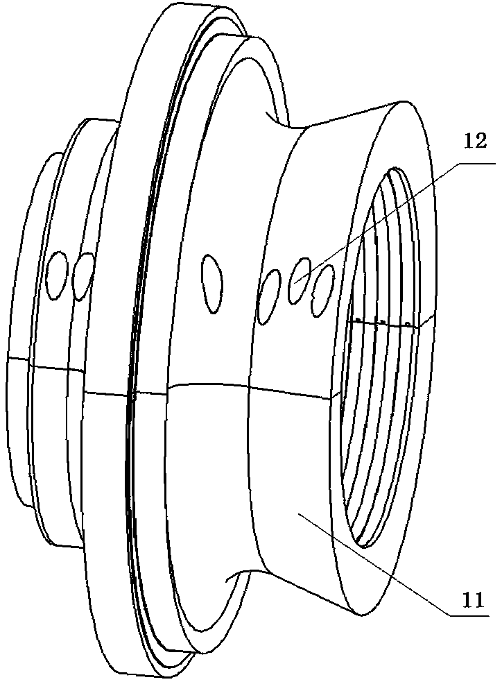
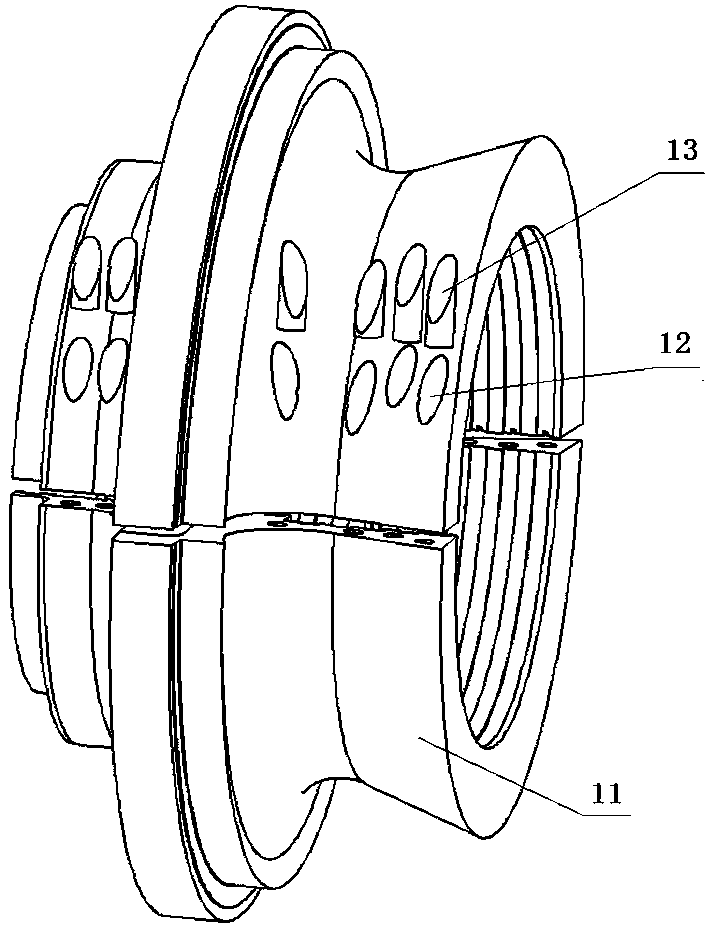
[0012] like Figure 1 to Figure 2 As shown, a high-efficiency steam turbine high and medium pressure intermediate seal body structure, the high and medium pressure intermediate pressure seal body 11 has a seal body high pressure steam inlet end profile 2 on the high pressure side, and a seal body high pressure steam outlet end profile 3; The profile line 6 of the medium-pressure steam inlet end of the gland body on the medium-pressure side, and the profile line 7 of the medium-pressure steam outlet end of the gland body; it is characterized in that: the profile line 2 of the high-pressure steam inlet end of the gland body and the type 1 cylinder of the high-pressure side Lines are matched, the profile line 3 of the high-pressure steam outlet end of the gland body matches the inlet of the high-pressure first-stage partition 4; the profile line 6 of the medium-pressure steam inlet end of the gland body matches the profile line 5 of the medium-pressure side cylinder Matching, the...


PUM


Abstract

The invention discloses a high-efficiency steam turbine mid-high pressure steam seal body structure, the high-medium pressure mid-pressure steam seal body has a steam seal body high-pressure steam inlet end molded line on the high-pressure side, a steam seal body high-pressure steam outlet end molded line; The profile line of the medium-pressure steam inlet end of the gland body and the profile line of the medium-pressure steam outlet end of the gland body; it is characterized in that: the profile line of the high-pressure steam inlet end of the gland body matches the profile line of the cylinder on the high-pressure side, and the The shape line of the high-pressure steam outlet end of the gland body matches the inlet of the high-pressure first-stage partition; the shape line of the medium-pressure steam inlet end of the gland body matches the shape line The profile line of the steam end is matched with the inlet of the medium-pressure first-stage partition; so that the cylinder forms smooth and smooth inlet channels from the high- and medium-pressure steam inlets to the inlets of the high- and medium-pressure first-stage partitions; and the The middle part of the molding line on both sides of the high and medium pressure intermediate pressure adopts a concave structure. The structure of the steam seal can form a 360°rotational, complete and smooth steam flow path, and has a high steam inlet efficiency.

Description

technical field [0001] The invention relates to a steam turbine steam seal body, in particular to a high-efficiency steam turbine high-medium-pressure steam seal body structure. Background technique [0002] The high and medium pressure intermediate gland is used in the high and medium pressure combined cylinder structure, and is located at the junction of the high pressure side and the medium pressure side of the cylinder, separating the high pressure part from the medium pressure part. The high- and medium-pressure cylinders, the steam seals between the high and medium pressures, and the high and medium pressure first-stage partitions respectively constitute the high and medium pressure steam inlet channels, which have an important impact on the steam flow and direction, thereby affecting the steam inlet efficiency. [0003] In previous designs and products, the integrity of the steam inlet channel and the expansion law of steam in the entire steam inlet channel were not f...

Claims


Application Information

Patent Timeline
Patent Type & Authority Patents(China)
IPC IPC(8): F01D11/04
CPCF01D11/04
Inventor 谭俊高宏喜段增辉欧楚雄陈海峰邱健陶功新靳浩徐滨
Owner DONGFANG TURBINE CO LTD
Why Eureka
Try Eureka