350mw supercritical three-cylinder two-row steam-humidity condensing steam turbine

A steam turbine and supercritical technology, applied in steam engine devices, combined engines, mechanical equipment, etc., can solve problems such as low cylinder efficiency and large cylinder flow loss, and achieve the effects of improving efficiency, reducing pressure, and excellent structural technology

Active Publication Date: 2017-08-15
HARBIN TURBINE +1
View PDF7 Cites 0 Cited by
  • Summary
  • Abstract
  • Description
  • Claims
  • Application Information

AI Technical Summary

Problems solved by technology

[0004] In order to solve the problems of large cylinder flow loss and low cylinder efficiency in existing steam turbines, the present invention further provides a 350MW supercritical three-cylinder two-row steam-humidity-condensing steam turbine

Method used


Image

  • 350mw supercritical three-cylinder two-row steam-humidity condensing steam turbine

Examples


specific Embodiment approach 1

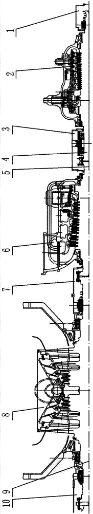
[0018] Specific implementation mode one: as figure 1 As shown, the 350MW supercritical three-cylinder two-row steam-humidity-condensing steam turbine in this embodiment includes a front bearing housing 1, a high-pressure cylinder 2, a first middle bearing housing 3, a steam turbine shafting high-pressure rotor 4, and a steam turbine shafting medium-pressure rotor 5. Medium pressure cylinder 6, second medium bearing box 7, low pressure cylinder 8, steam turbine shaft low pressure rotor 9 and rear bearing box 10, front bearing box 1, first middle bearing box 3, second middle bearing box 7 and rear The bearing boxes 10 are all installed on the frame with a floor structure, the high-pressure cylinder 2 is supported on the front bearing box 1 and the first middle bearing box 3 through the upper cat claws, and the medium-pressure cylinder 6 is supported on the first middle bearing box through the upper cat claws 3 and the second middle bearing box 7; the low-pressure cylinder 8 is i...

specific Embodiment approach 2

[0025] Specific implementation mode two: as figure 1 As shown, in this embodiment, the high-pressure cylinder 2 and the medium-pressure cylinder 6 are all single-flow cylinders, and the low-pressure cylinder 8 is a double-flow cylinder. Such a design can effectively balance the axial thrust of the rotor and make the overall design of the shaft system more reasonable. Other components and connections are the same as those in the first embodiment.

specific Embodiment approach 3

[0026] Specific implementation mode three: as figure 1 As shown, the high-pressure main steam regulating combined valve in this embodiment is symmetrically arranged on both sides of the high-pressure cylinder 2, and the high-pressure main steam regulating combined valve is respectively connected to the upper and lower sides of the high-pressure cylinder 2 with air guide pipes, and the high-pressure main steam regulating combined valve and the foundation are Rigid support. Designed in this way, the cylinder flow pattern set up in this way can not only improve the efficiency of each cylinder, but also effectively shorten the axial dimension of the unit, control the length of the final stage blade and reduce the axial thrust of the rotor. Other compositions and connections are the same as those in Embodiment 1 or 2.


PUM


Abstract

The invention provides a 350 MW supercritical three-cylinder two-exhaust wet condensing steam turbine, and relates to a steam turbine. The problems that a conventional steam turbine is high in cylinder flow loss and low in cylinder efficiency are solved. The 350 MW supercritical three-cylinder two-exhaust wet condensing steam turbine is characterized in that a front bearing box, a first middle bearing box, a second middle bearing box and a rear bearing box are all mounted on a rack through grounding structures, a high-pressure cylinder is supported on the front bearing box and the first middle bearing box through upper cat-pads, an intermediate-pressure cylinder is supported on the first middle bearing box and the second middle bearing box through upper cat-pads, a low-pressure cylinder is mounted on the rack through a grounding structure, the high-pressure cylinder, the intermediate-pressure cylinder and the low-pressure cylinder are sequentially serially arranged in the length direction and all adopt inner-outer dual-layer cylinder structures, a steam turbine shafting high-pressure rotor, a steam turbine shafting intermediate-pressure rotor and a steam turbine shafting low-pressure rotor are connected through rigid flange couplings, and the steam turbine shafting high-pressure rotor and the steam turbine shafting low-pressure rotor both adopt dual-supporting structures. The 350 MW supercritical three-cylinder two-exhaust wet condensing steam turbine is used in the field of coal-fired power generation.

Description

technical field [0001] The invention relates to a wet-condensing steam turbine, in particular to a 350MW supercritical three-cylinder two-row steam wet-condensing steam turbine. Background technique [0002] As the core equipment for coal-fired power generation, the technology and products of steam turbines will aim at improving efficiency, and usher in a new development milestone based on the research and development of high-temperature materials and a series of advanced technologies. The core of the new round of coal-fired power generation technology development is to vigorously promote the improvement of product design technology, manufacturing process and thermal system optimization technologies, and involves improving steam parameters, optimization design of flow parts, structural optimization, cold end optimization, thermal cycle And system optimization, advanced manufacturing technology and other fields. The depth and level of development in these technical fields de...

Claims


Application Information

Patent Timeline
Patent Type & Authority Patents(China)
IPC IPC(8): F01D13/00F01D25/28F01D5/02F01D5/08F01K7/32
CPCF01D5/02F01D5/08F01D13/00F01D25/28F01K7/32
Inventor 张秋鸿王文斌陆伟高良军王强耿金环高敏任贵龙
Owner HARBIN TURBINE
Why Eureka
Try Eureka