Flow channel tube assembling device

A technology of runners and channels, which is applied in the field of paper tube assembly devices, can solve the problems of low stability in use, high cost of man-hours, and low quality, and achieve the effects of neat and regular shapes, good overall structural strength, and high efficiency

Active Publication Date: 2011-11-30
浏阳市中洲机械科技有限公司
View PDF0 Cites 0 Cited by
  • Summary
  • Abstract
  • Description
  • Claims
  • Application Information

AI Technical Summary

Problems solved by technology

[0002] At present, the paper tube combination methods and devices mainly include manual gluing and manual folding combination, and manual gluing and mechanical shrinkage and folding combination. They have problems: first, the combined paper tube is easy to deform and irregular, and the quality is not high; The efficiency is low, and the cost of man-hours is high; moreover, the structure of the existing barrel assembly device is relatively complicated, and the stability of use is low, which is not conducive to the automatic production of large-scale assembly line

Method used


Image

  • Flow channel tube assembling device
  • Flow channel tube assembling device
  • Flow channel tube assembling device

Examples


Embodiment 1

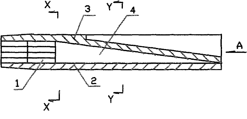
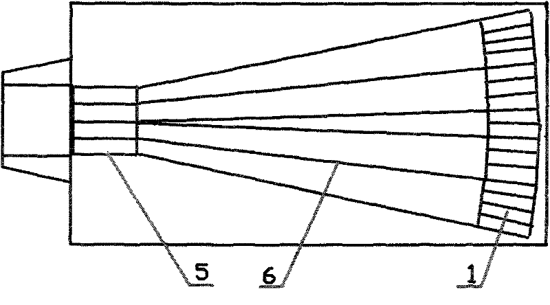
[0014] Example 1, in Figure 1 to Figure 5 Among them, the flow channel assembly device includes two molded bodies (namely upper molded body 3 and lower molded body 2) that can be opened and closed each other, two left ends between upper molded body 3 and lower molded body 2 Each end has a storage cylinder cavity 5 with an opening. The cross section of the storage cylinder cavity is square. The horizontal direction of the block is a strip-shaped bump 6. The cross-section of the bump is triangular, and the tip and the bump are transitioned with rounded corners. The horizontal direction of the bump is inclined, and the right end of the bump (lower) Located on the joint surface of the lower mold body, the left end (high point) of the bump is connected to the top surface of the opening of the storage chamber, the right ends of the two protrusions are arranged at intervals, and the left ends of the two protrusions are closely connected to the side of the storage chamber after they ...

Embodiment 2

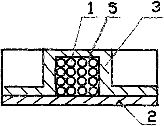
[0015] Embodiment 2, can refer to Figure 1 to Figure 5 The difference between the present embodiment 2 and the embodiment 1 is that only one bump 6 is set on the lower mold body 2, and a groove 7 corresponding to the shape and position of a bump is set in the upper mold body. An inverted V-shaped channel 4 is formed between the groove and the groove, and a rectangular storage chamber 5 is provided at the left end between the upper mold body 3 and the lower mold body 2. In addition, the present embodiment 2 and the implementation Example 1 has the same structure. In this embodiment 2, there are 8 paper tubes in rows, and four paper tubes 1 are placed on the side of the protrusion to form a 2×4 arrangement. Glue is sprayed on the paper tubes, and then the paper tubes are moved along the The channel moves synchronously, so that the paper tube is folded horizontally in the channel and squeezed and pushed into the cavity of the storage tube to form a rectangular combined paper tu...


PUM


Abstract

The invention discloses a flow channel tube assembling device, which comprises two molded bodies which can be separate and combined, wherein a convex block (6) is arranged on one molded body, and a groove (7) corresponding to the convex block is arranged on the other molded body; a channel (4) is formed between the convex block and the groove; a tube storing cavity (5) communicated with the channel is arranged between the molded bodies; and paper tubes (1) which are stringed are folded horizontally along the channel under the action of an external power and pressed into the tube storing cavity to be assembled. In the invention, the stringed paper tubes, on which an adhesive such as glue is sprayed in advance, are placed at the position of the channel inlet of the flow channel tube assembling device flatly first; and then the stringed paper tubes are moved and folded horizontally and synchronously along a channel formed by the convex block and the groove and pressed into the tube storing cavity by the external force to form a rectangle or square combined paper tube corresponding to the tube storing cavity in shape. The combined paper tube has ordered and regular shape arrangement and high overall structural strength; the tube assembly efficiency is high; time and labor are reduced; assembly line operation can be formed; and large-scale automatic production can be realized.

Description

technical field [0001] The invention relates to a paper tube assembly device, in particular to a paper tube flow channel assembly device. Background technique [0002] At present, the paper tube combination methods and devices mainly include manual gluing and manual folding combination, and manual gluing and mechanical shrinkage and folding combination. They have problems: first, the combined paper tube is easy to deform and irregular, and the quality is not high; The efficiency is low, and the cost of man-hours is high; moreover, the structure of the existing barrel assembly device is relatively complicated, and the stability of use is low, which is not conducive to the automatic production of large-scale assembly line. Contents of the invention [0003] Aiming at the problems existing in the combination of paper tubes in the above-mentioned prior art, the present invention proposes a flow channel tube assembly device that not only has a simple structure and is easy to op...

Claims


Application Information

Patent Timeline
Patent Type & Authority Patents(China)
IPC IPC(8): B31C5/00
Inventor 雷鸣蔡忠伟
Owner 浏阳市中洲机械科技有限公司
Why Eureka
Try Eureka