Neutron scintillator position sensitive detector testing system and method

A technology of sensitive detector and test system, applied in the field of nuclear physics detection, can solve the problems of difficult control of trigger source quality, difficult lateral comparison, and difficulty in matching measurement requirements, and achieves the effect of efficient, fast and detailed measurement and stable output.

Inactive Publication Date: 2018-04-10
DONGGUAN UNIV OF TECH +1
View PDF6 Cites 0 Cited by
  • Summary
  • Abstract
  • Description
  • Claims
  • Application Information

AI Technical Summary

Problems solved by technology

These methods have complex testing system and low efficiency
In addition, the relevant management regulations on radioactive sources are strict, and many experimental trigger sources still have defects such as difficult quality control, which makes it difficult to well meet the performance requirements of scintillation detection position-sensitive nuclear detectors.
For example, special-purpose experimental testing requires on-site layout, and the testing system has long-term uncertainty. Once the measurement requirements and environment change, the experiment will almost have to be re-scaled, so it is time-consuming, poor in versatility, and different experiments It is difficult to compare horizontally between environments
Furthermore, in addition to being strictly restricted by the relevant management regulations of radioactive sources, the calibration of radioactive sources often has defects such as difficult control of activity / triggering, which makes it difficult to achieve a good match with measurement requirements
The above factors make it difficult for traditional detection systems to control the production quality of scintillator detectors well

Method used


Image

  • Neutron scintillator position sensitive detector testing system and method
  • Neutron scintillator position sensitive detector testing system and method
  • Neutron scintillator position sensitive detector testing system and method

Examples


Embodiment Construction

[0023] In order to describe the technical content, structural features, achieved objects and effects of the present invention in detail, the following detailed description is given in conjunction with the embodiments and the accompanying drawings.

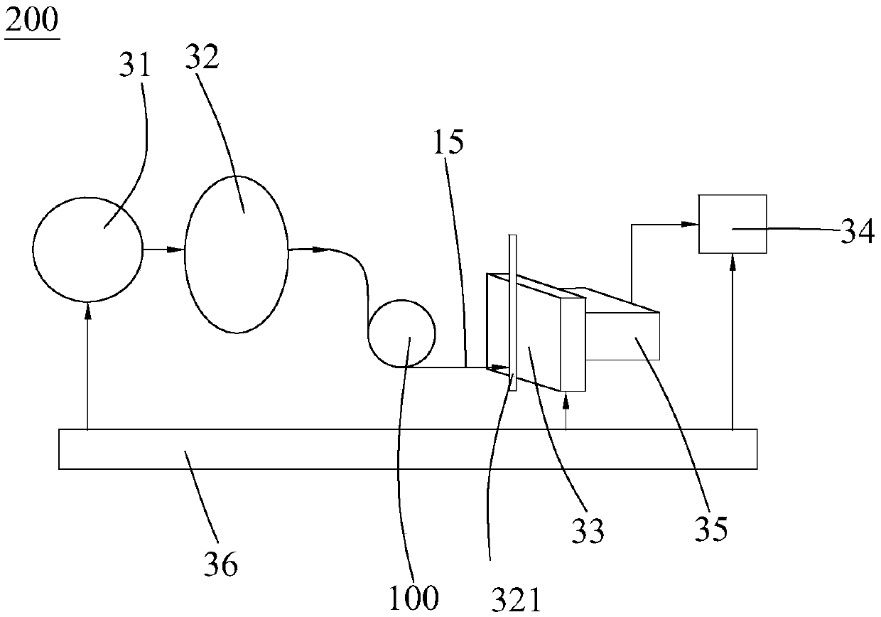
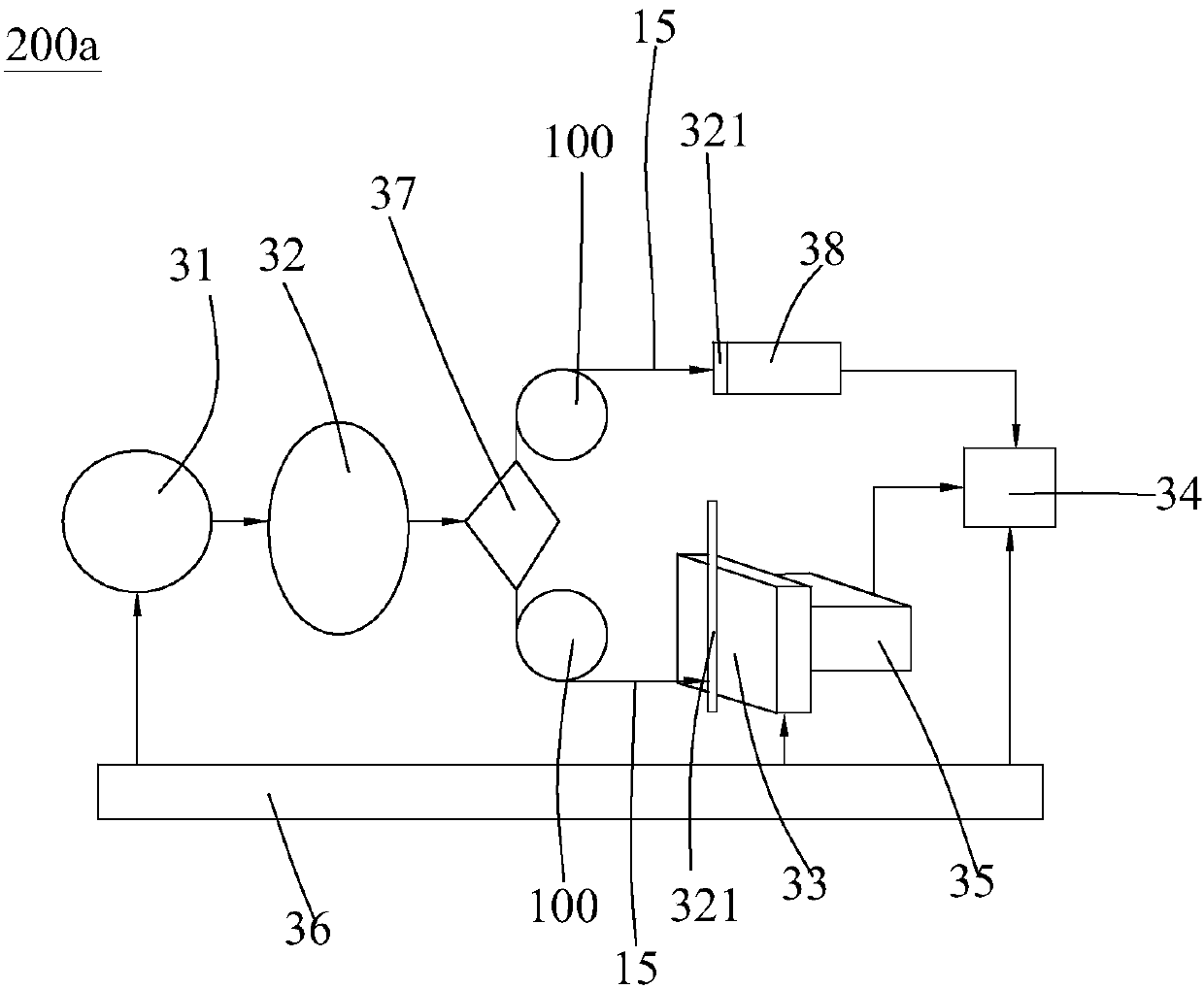
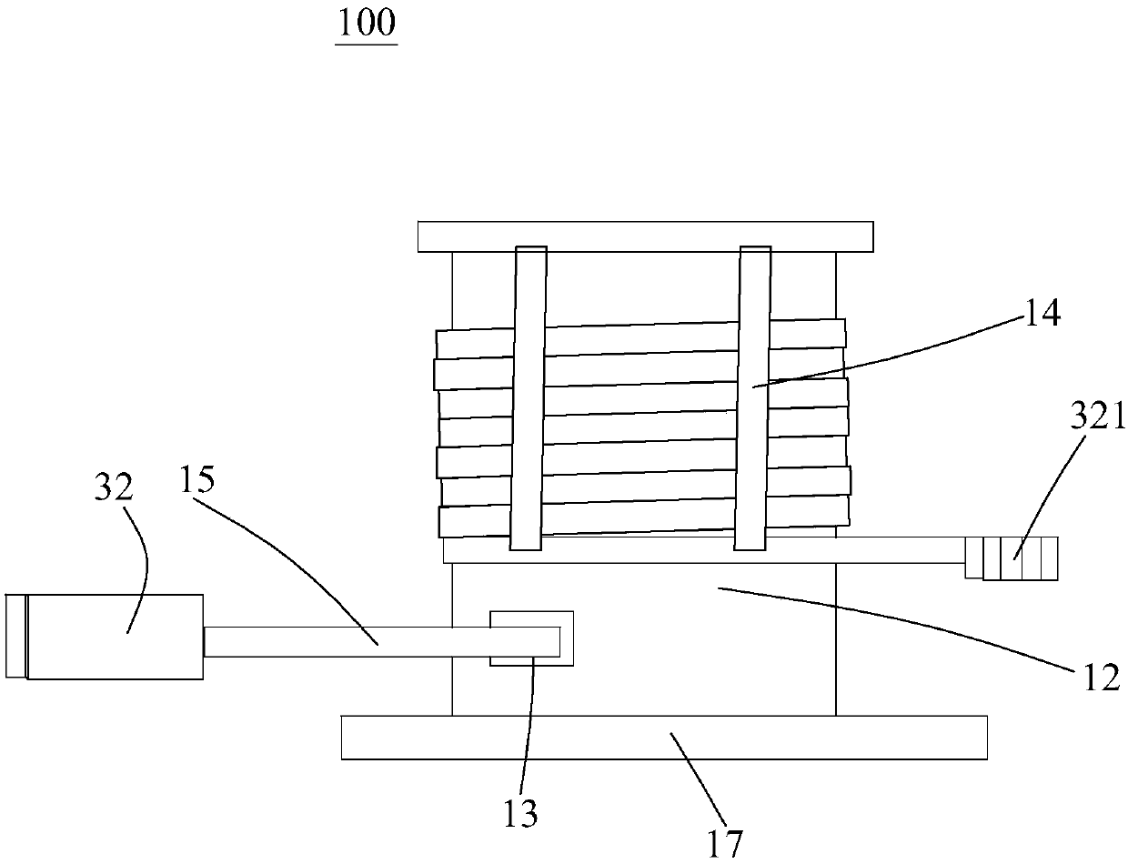
[0024] refer to figure 1 The present invention discloses a neutron scintillator position-sensitive detector testing system 200, comprising a pulsed light source simulation device 31, an optical processing module 32, a mechanical scanning platform 33 and a data acquisition module 34, the pulsed light source simulation device 31 outputs pulsed light After the optical processing module 32 attenuates, polarizes and expands the pulsed optical signal, it is collimated by a fiber collimator 321 and fixed on the mechanical scanning platform 33, and the The pulsed light signal is irradiated on the test point of the wave-shift optical fiber of the neutron scintillator position-sensitive detector 35 to be tested, and the pulsed light signal o...


PUM


Abstract

The invention discloses a system for testing a neutron scintillator position sensitive detector. The system comprises a pulsed light source simulator, an optical processing module, a mechanical scanning platform and a data acquisition module. The pulsed light source simulator outputs pulsed light signals; the pulsed light signals are processed through the optical processing module by means of attenuation, polarization and beam expanding, collimated by an optical fiber collimator and fixed to the mechanical scanning platform; the pulsed light signals irradiate to a test point of a wavelength-shifting optical fiber of the neutron scintillator position sensitive detector to be tested, and output photons to a tested photomultiplier having multiple channels through the wavelength-shifting optical fiber, and finally the data acquisition module acquires tested signals of the tested photomultiplier. According to the system, a light source emitted from the neutron scintillator is simulated through pulsed laser, and performance parameter of the signals from the wavelength-shifting optical fiber to the different channels of the photomultiplier are acquired, thus, detection and test of nuclear detectors in non-radioactive environments are achieved.

Description

technical field [0001] The invention belongs to the field of nuclear physics detection. The invention relates to a 2D neutron scintillator position-sensitive detector testing system, in particular to the use of laser beams to simulate neutron light spots on a scintillation screen to measure and test each channel of a scintillator position-sensitive nuclear detector without the need for radiation Reference information such as the location of the source or additional other detectors to aid in the measurement. Background technique [0002] Neutron detectors based on new scintillators and photoelectric readout structures have developed rapidly in recent years, especially doped scintillation detectors. However, neutron scintillator position-sensitive detectors mostly use photoelectric detectors in the detection-readout link. Due to objective reasons such as production process, it is difficult to keep the performance parameters of each readout channel consistent for amplifier dev...

Claims


Application Information

Patent Timeline
Patent Type & Authority Patents(China)
IPC IPC(8): G01T3/06
CPCG01T3/06
Inventor 李仪滕海云孙志嘉唐斌杨雷王艳凤许虹赵晓芳陈平平
Owner DONGGUAN UNIV OF TECH
Why Eureka
Try Eureka