Fiber bending mode eliminating device and method

A bending and mold elimination technology, applied in the field of nuclear physics detection, can solve the problems of damage stability guarantee, manufacturing difficulty, unfavorable transmission power, etc.

Inactive Publication Date: 2017-05-31
DONGGUAN UNIV OF TECH
View PDF5 Cites 0 Cited by
  • Summary
  • Abstract
  • Description
  • Claims
  • Application Information

AI Technical Summary

Problems solved by technology

[0005] The inner diameter of the single-mode fiber is limited to the range of the transmission wavelength, which is not only difficult to manufacture and high in cost, but also not conducive to the transmission of power, and there are also matching restrictions on the light source
Once the inner core diameter is expanded to transmit higher power, or the transmission light source is replaced in different measurement occasions, the wavelength will change, which will lead to the introduction of high-order modes and destroy the original stability guarantee
In addition, on some special bending radii, there are unique transmission modes, and the attenuation coefficient of the corresponding mode will decrease sharply
The above two sources lead to the limitations of single-mode optical fiber transmission of analog signals, and are also the reason why multi-mode optical fibers cannot guarantee stable long-distance transmission of constant analog signals
[0006] Furthermore, in order to calibrate each channel of the photomultiplier tube, the output optical fiber needs to be fixed on a mechanical platform, and the entire wave-shifting optical fiber plane is scanned. In this way, during the scanning movement, the optical fiber is bent, resulting in inconsistent optical output power at different positions. , loses the meaning of calibration

Method used


Image

  • Fiber bending mode eliminating device and method
  • Fiber bending mode eliminating device and method
  • Fiber bending mode eliminating device and method

Examples


Embodiment Construction

[0018] In order to describe the technical content, structural features, achieved goals and effects of the present invention in detail, the following will be described in detail in conjunction with the embodiments and accompanying drawings.

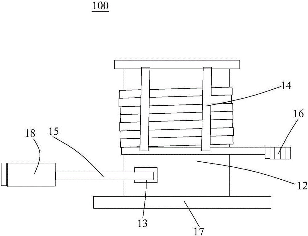
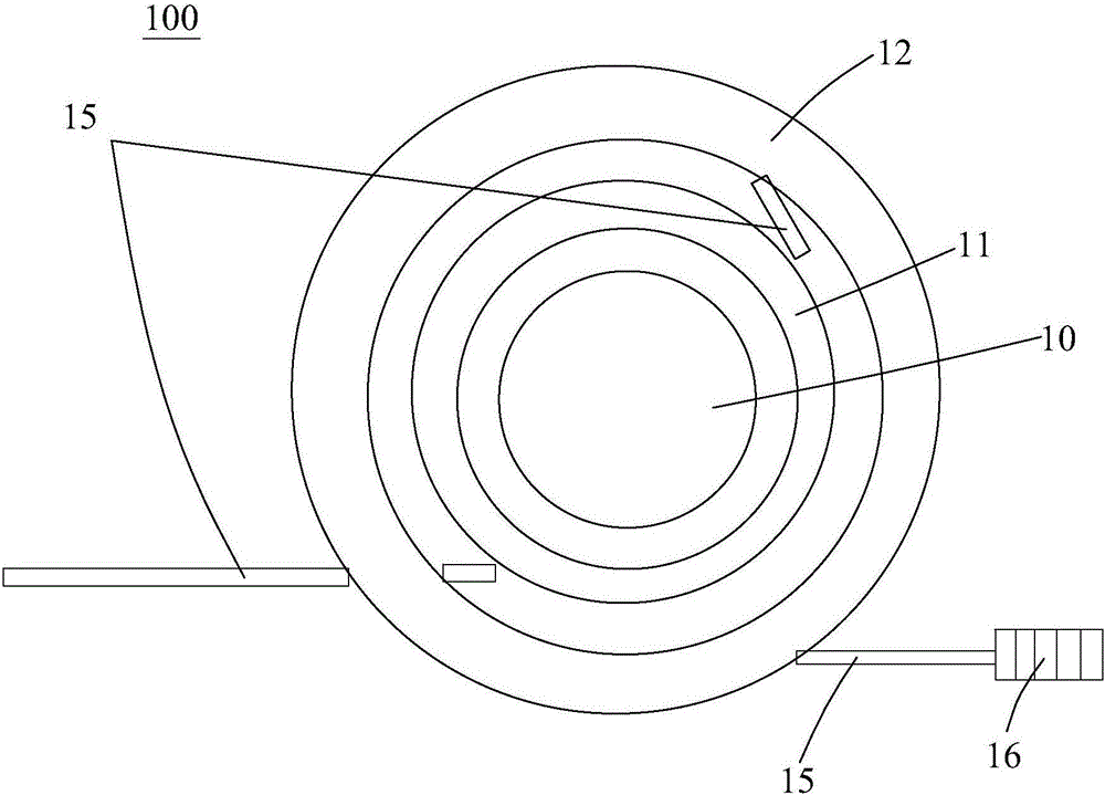
[0019] refer to figure 1 and figure 2 , the present invention discloses an optical fiber bending mode elimination device 100, comprising an annular inner coiling mold 11, an outer coiling mold 12 and a multimode optical fiber 15 surrounding the inner coiling mold 11 at a certain distance, the outer coiling mold 12 is provided with a through hole 13, a part of the multimode optical fiber 15 is wound on the inner coiling mold 11, and the other part passes through the through hole 13 and is wound on the outer coiling mold 12, so that the multimode optical fiber 15 forms a small-radius coiled portion wound on the inner coiled mold 11 and a large-radius coiled portion wound on the outer coiled mold 12 . Among them, since the core diameter of...


PUM


Abstract

The invention discloses a fiber bending mode eliminating device and method; a multi-mode fiber is wound with an inner winding tool and an outer winding tool by means of double-curvature winding, so that the multi-mode fiber forms a small-radius winding portion wound on the inner winding tool and a large-radius winding portion wound on the outer winding tool. The multi-mode fiber is used as a transmission medium and is pre-wound according to two different radiuses, a higher-mode component coupled into the fiber is attenuated effectively with the small-radius winding portion, bending transmission mode possibly excited in previous step is eliminated with the large-radius winding portion, the inhibition on higher mode by the multi-mode fiber is achieved, output optical intensity is stable, an optical signal with mode eliminated outputs optical power that is kept constant during fiber moving, and using additional other detectors to assist in measuring position and other reference information during measurement of a scintillator position-sensitive nuclear detector is not required accordingly.

Description

technical field [0001] The invention belongs to the field of nuclear physics detection. The invention is an optical fiber mode elimination device for optical transmission in a neutron scintillator position-sensitive detector calibration system, especially related to the scene where the output intensity is required to be stable, so that most of the high-order modes of the laser light source can The components of the optical fiber are sufficiently attenuated to ensure that the output optical power of the fiber is stable during the movement. Background technique [0002] Although there are many types of large-area imaging scintillator neutron detectors, the basic principles are similar, and the detection of particles is realized through fluorescence excitation and photoelectric conversion. The neutron scintillator position-sensitive detector is mainly composed of scintillation screen, wave-shifting optical fiber, photomultiplier tube, etc. The scintillator absorption wavelengt...

Claims


Application Information

Patent Timeline
IPC IPC(8): G01T7/00G01T3/06
CPCG01T3/06G01T7/005
Inventor 李仪滕海云孙志嘉唐斌杨雷陈平平王艳凤许虹
Owner DONGGUAN UNIV OF TECH
Why Eureka
Try Eureka