Drive assembly and process box using same
A technology for driving components and driving components, applied in the field of driving components and processing cartridges, can solve the problem of not being able to install the processing cartridges smoothly.
- Summary
- Abstract
- Description
- Claims
- Application Information
AI Technical Summary
Problems solved by technology
Method used
Image
Examples
Embodiment 1
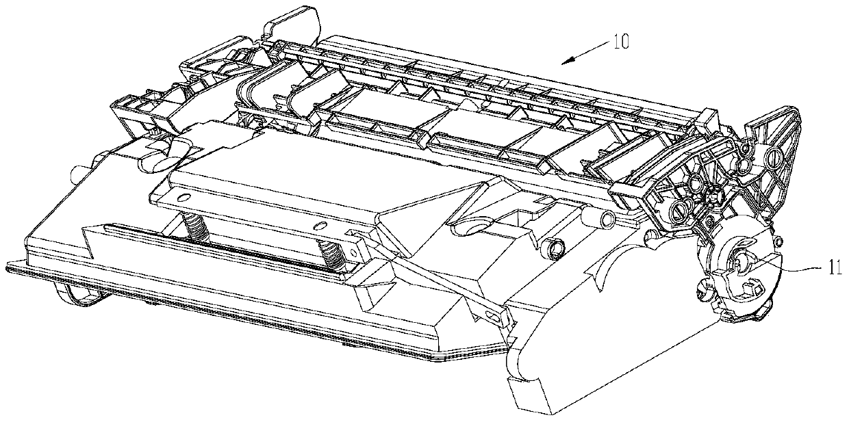
[0190] figure 1 A perspective view of a process cartridge provided in the present application, Figure 10 is the process cartridge, and a power socket 11 for receiving rotational power from an image forming device is disposed at a longitudinal end of the process cartridge 10 .
[0191] The following will introduce in detail how to use the solution of the present application to realize the transmission of power through the control mechanism controlling the engagement of the power socket and the drive mechanism in the image forming device.
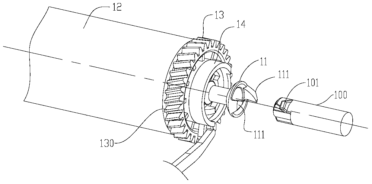
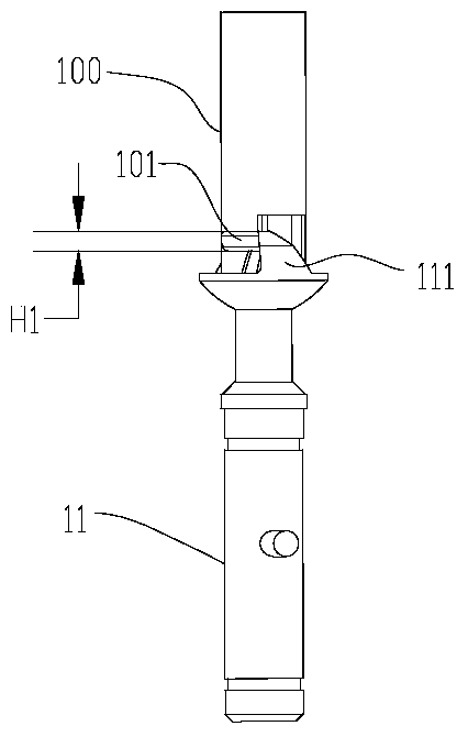
[0192] figure 2 It is a partial structural view of this embodiment. A hub 13 is arranged on the longitudinal end of the process box, and a positioning ring 14 is coaxially arranged on the hub, and the power receiving port 11 is arranged on the hub 13 through the positioning ring 14 . After the process cartridge is installed into the image forming device, the power receiving port 11 is engaged with the driving mechanism 100 in the image for...
Embodiment 2
[0244] Figure 24 Shown is an exploded view of yet another embodiment of the present application.
[0245] The first embodiment provided by the present application is to control the rotation of the hub 13 through the control mechanism, so as to drive the rotation of the power socket 11 .
[0246] However, in the embodiment provided by this embodiment, the power receiving port 011 is controlled to rotate by the control mechanism during the process of installing the process cartridge. During this process, the power receiving port 011 rotates relative to the hub 013 .
[0247] Such as Figure 24 As shown, the control mechanism includes a positioning ring 014, a first guide sleeve 015A, a second guide sleeve 015B, and an intermediate connecting part 016; the positioning ring 014 is also provided with an adjustment part 0142.
[0248] The power receiving port 011 passes through the positioning ring 014, the first guide sleeve 015A, and the second guide sleeve 015B are arranged on...
Embodiment 3
[0255] Figure 27 It is another embodiment of the present application. The present application also provides a solution, that is, only the control mechanism is required to control the rotation of the power socket 11 to avoid interference between the process cartridge and the drive mechanism of the image forming device during installation. That is to say, the control mechanism of the first embodiment does not include the guide sleeve 15, that is, when the positioning ring rotates, the power receiving port 11 does not slide along the direction of its rotation axis, and the control mechanism is also used to control the power receiving port 11. to rotate.
[0256] In this embodiment, the end of the claw 111 of the power receiving port 11 is set to be an inclined surface or a curved surface; when the process is installed along the X direction, the claw of the power receiving port 11 The end 1111 of 111 is in contact with the protruding part 101 of the driving mechanism 100, and t...
PUM
 Abstract
Description
Claims
Application Information
 - R&D
- Intellectual Property
- Life Sciences
- Materials
- Tech Scout
- Unparalleled Data Quality
- Higher Quality Content
- 60% Fewer Hallucinations
Browse by: Latest US Patents, China's latest patents, Technical Efficacy Thesaurus, Application Domain, Technology Topic, Popular Technical Reports.
© 2025 PatSnap. All rights reserved.Legal|Privacy policy|Modern Slavery Act Transparency Statement|Sitemap|About US| Contact US: help@patsnap.com


