Billboard device

A technology of billboards and mounting racks, applied in the field of cargo transportation, can solve the problems of reducing the work efficiency of staff and inconvenient operation

Inactive Publication Date: 2017-06-13
YIWU KAIJING IMPORT & EXPORT
7 Cites 0 Cited by

AI-Extracted Technical Summary

Problems solved by technology

[0002] Nowadays, billboards are widely used. Billboards are used to display the product information of enterprises or merchants and play a role in publicity. As the products of enterprises or merchants are updated, the content displayed on billboards also needs to be updated. Billboards are generally in...

Abstract

The invention discloses a billboard device which comprises an installation frame and a clamping column, wherein a billboard is fixedly arranged on the front end surface of the clamping column; a guide convex rod which is located at the center and is expanded from front to back is arranged on the bottom wall of an installation cavity of the installation frame; a guide concave hole matched with the guide convex rod is formed in the bottom wall of the clamping column; left and right corresponding promoting grooves are formed in the bottom wall of the clamping column; first limiting grooves are correspondingly formed in two sides of the promoting grooves; fluctuation devices poking into the promoting grooves are correspondingly arranged at the left and right of the bottom wall of the installation cavity of the installation frame; each fluctuation device comprises a movable groove and a movable plate, wherein the inlet of the movable groove faces the installation cavity, and the movable plate is movably arranged in the movable groove; a threaded sleeve shell is fixedly arranged at the center of the lower end of the movable plate; a screw rod is arranged in the threaded sleeve shell in screw-thread fit; and the screw rod is connected with an electric rotating machine fixedly arranged at the bottom end of the movable groove.

Application Domain

Boards

Technology Topic

EngineeringScrew thread

Image

  • Billboard device
  • Billboard device
  • Billboard device

Examples

  • Experimental program(1)

Example Embodiment

[0020] All features disclosed in this specification, or all disclosed steps in a method or process, may be combined in any way except mutually exclusive features and/or steps.
[0021] Any feature disclosed in this specification (including any accompanying claims, abstract and drawings), unless expressly stated otherwise, may be replaced by other equivalent or alternative features serving a similar purpose. That is, unless expressly stated otherwise, each feature is but one example of a series of equivalent or similar features.
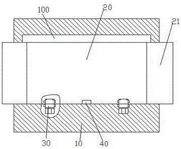
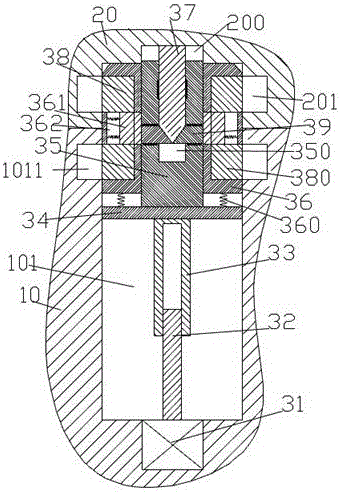
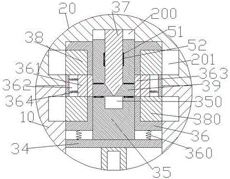
[0022] like Figure 1-4 As shown, a billboard device of the present invention includes an installation frame 10 and a clamping column 20 , the front end surface of the clamping column 20 is fixedly provided with a billboard 21 , and the bottom wall of the installation cavity 100 of the installation frame 10 is arranged on the bottom wall of the installation cavity 100 . A guide protruding rod 40 is provided at the center of the left and right and unfolded front and rear. The bottom wall of the clamping column 20 is provided with a guiding concave hole matched with the guiding protruding rod 40. The bottom wall of the clamping post 20 There are two corresponding facilitation grooves 200 on the left and right, and first restraint grooves 201 are correspondingly provided on both sides of the facilitation groove 200. The bottom wall of the installation cavity 100 of the mounting frame 10 is provided with correspondingly poking the facilitation grooves on the left and right sides. The fluctuation device 30 of the groove 200, the fluctuation device 30 includes a movable groove 101 with an entrance facing the installation cavity 100 and a movable plate 34 movably installed in the movable groove 101, the lower end of the movable plate 34 is in the center A threaded casing 33 is fixedly installed at the threaded casing 33, and a screw rod 32 is threadedly installed in the threaded casing 33. The screw rod 32 is connected with the electric transfer machine 31 fixedly installed at the bottom end of the movable groove 101. The movable plate 34 A placement block 36 is installed on the upper end through a first elastic piece 360, a hole that is unfolded up and down is arranged at the center of the placement block 36, and a movable frame 35 is movably installed in the hole, and the first elastic piece 360 ​​is used to attach the placement block. 36 is lifted upward and the upper end surface of the mounting block 36 is flush with the upper end of the movable frame 35, the lower end of the movable frame 35 is fixedly connected with the movable plate 34, and the movable frame 35 is provided with an inlet facing upward. The pressing groove 350 is provided with a vertical pressing column 37 movably installed in the pressing groove 350 . The left and right sides of the movable frame 35 are correspondingly provided with compression grooves communicating with the pressing groove 350 . A pressing post 39 is installed, the upper ends of the two side walls of the movable groove 101 are respectively provided with second restraining grooves 1011 on the left and right, and the seating block 36 is also installed with the first restraining groove 201 and the second restraining groove 201 The engaging device matched with the groove 1011.
[0023] Beneficially, the engaging device includes an upper movable slot and a lower movable slot corresponding to the left and right in the setting block 36, and a hole 362 communicating with the upper movable slot and the lower movable slot, and the inner side of the hole 362 is connected with the upper movable slot 362. The holes communicate with each other, the upper movable slot and the lower movable slot are respectively movably installed with the upper movable arm 38 and the lower movable arm 380, and the hole 362 can be movably installed with a butt bar 361 left and right, and the abutment bar 361 and the The upper limit movable arm 38 and the lower limit movable arm 380 are fixedly connected, the inner end of the butt bar 361 is provided with a protruding block 363 that protrudes inward, and the outer end of the butt bar 361 and the outer end wall of the hole 362 are fixedly installed. The second elastic piece 364 is used for pressing the protruding block 363 to the inner end of the hole 362 .
[0024] Beneficially, the inner end surface of the pressing column 39 is provided with a pressing slope, and the lower end of the vertical pressing column 37 is provided with a first pressing slope matched with the pressing slope.
[0025] Beneficially, first guide protruding blocks 51 are fixedly arranged on both end surfaces of the vertical pressing post 37 , and the first guiding protruding blocks 51 are movably installed on the side walls of the pressing groove 350 . The first guide movable groove 52 is also provided with a third elastic piece 52 connected with the first guide protrusion block 51, and the third elastic piece 52 is used to The shape is pressed against the column 37 upwards.
[0026] Beneficially, the upper and lower end surfaces of the pressing column 39 are fixedly provided with second guide protrusion blocks, and the second guide protrusion blocks are movably installed in the second guide movable grooves provided in the upper and lower end walls of the compression grooves. and the second guide movable groove is further provided with a fourth elastic piece connected with the second guide protrusion block, and the fourth elastic piece is used to bias the pressing column 39 inward.
[0027]In the initial state, the vertical pressing post 37 protrudes upward under the action of the third elastic piece 52 and is flush with the bottom wall of the mounting cavity 100 of the mounting frame 10 , thereby allowing the latching post 20 to push into the mounting cavity 100 of the mounting frame 10, the pressing post 39 shrinks inwardly under the action of the fourth elastic piece without acting on the protruding block 363, the upper limit arm 38 and the lower limiter The arm 380 also shrinks inwardly under the action of the second elastic piece 364 , thereby allowing the mounting block 36 to move upward; when the latching post 20 is pushed into the installation along the guiding protruding rod 40 After the installation cavity 100 of the rack 10 is installed, the electric rotating machine 31 is activated, and the electric rotating machine 31 drives the screw rod 32 to rotate, and drives the threaded casing 33 to move upward, and the threaded casing 33 lifts the The movable plate 34 moves upward, and when the upper end of the placement block 36 is connected to the promotion groove 200, the motor 31 continues to run, and the movable frame 35 is driven to overcome the first elastic piece 360 ​​to continue to move upward, and the The vertical pressing column 37 moves downward relative to the movable frame 35, and the vertical pressing column 37 will move the pressing column under the action of the first pressing slope surface and the pressing slope surface 39 is pushed out, and the pressing post 39 will push the protruding block 363 to move to the outside after it protrudes out, thereby driving the upper limit boom 38 and the lower limit boom 380 to extend outward and poke in respectively. In the first restraint groove 201 and the second restraint groove 1011 , when the movable frame 35 moves upward to the highest point, the electric rotating machine 31 is stopped. At this time, the upper movable arm 38 and the lower limit Under the action of the boom 380 , the shaking of the clamping column 20 in the vertical direction can be restricted, and under the action of the mounting block 36 , the movement of the clamping column 20 in the lateral direction can be restricted; When the clamping post 20 is taken out, the electric rotating machine 31 is rotated in the reverse direction, which drives the movable plate 34 to move downward, and the vertical pressing post 37 can be opposite to any other position under the action of the first elastic piece 360 ​​. The movable frame 35 moves upward, and the pressing column 39 retracts inward under the action of the fourth elastic piece, so that the upper limit movable arm 38 and the lower limit movable arm 380 are under the action of the second elastic piece 364 It also retracts inward. When the upper limit boom 38 and the lower limit boom 380 are fully retracted inward, the placement block 36 can slide down with the movable plate 34, and the movable plate 34 moves to the lowest point. Stopping the electric rotating machine 33 returns to the initial state, thereby allowing the snap-on post 20 to be taken out.
[0028] The beneficial effect of the present invention is: in the initial state, the vertical pressing post protrudes upward under the action of the third elastic piece and is flush with the bottom wall of the mounting cavity of the mounting frame, thereby allowing the snap-connecting post to be pushed into the mounting frame for installation In the cavity, the pressing column shrinks inwardly under the action of the fourth elastic piece without acting on the protruding block, and the upper limit moving arm and the lower limit moving arm also shrink inwardly under the action of the second elastic piece, thereby allowing the placement block to move upwards;
[0029] The clamping post is pushed into the mounting cavity of the mounting frame along the guiding protruding rod to realize the positioning of the promotion groove and the movable groove, so as to facilitate the insertion of the placement block into the promotion groove;
[0030] When the electric rotating machine drives the movable plate to move upward and the upper end of the placement block is connected to the promoting groove, the electric rotating machine continues to run, and drives the movable frame to overcome the first elastic piece to continue to move upward, and the vertical pressing column moves downward relative to the movable frame, while the vertical pressing Under the action of the first pressing against the slope surface and the pressing against the slope surface, the leaning column will push the pressing column outward, and after the pressing column extends outward, it will push the protruding block to move to the outside, thereby driving the upper limit boom. and the lower limit boom protrude outwards and poke into the first limit slot and the second limit slot respectively, when the movable frame moves up to the highest point, under the action of the upper limit boom and the lower limit boom, the The clamping post shakes in the vertical direction, and under the action of the placement block, the movement of the clamping post in the lateral direction can be restricted, so that the clamping post can be stably clamped in the installation cavity of the mounting frame;
[0031] After the reverse operation of the electric rotating machine, the movable plate can be driven to move downward, the vertical pressing column can move upward relative to the movable frame under the action of the first elastic piece, and the pressing column is retracted inward under the action of the fourth elastic piece. Therefore, the upper limit boom and the lower limit boom are also retracted inward under the action of the second shrapnel. When the upper limit boom and the lower limit boom are fully retracted inward, the placement block can slide down with the movable plate, and the movable plate moves to the lowest level. After clicking, stop the electric switch and return to the initial state, thus allowing the clamping column to be taken out, and it is also convenient for the clamping column to be pushed in the next time;
[0032] The device of the invention is convenient to use, has high safety, and can greatly increase the convenience of replacing the billboard.
[0033] The above are only specific embodiments of the invention, but the protection scope of the invention is not limited to this, and any changes or substitutions that are not conceived of without creative work should be included within the protection scope of the invention. Therefore, the protection scope of the invention should be subject to the protection scope limited by the claims.

PUM

no PUM

Description & Claims & Application Information

We can also present the details of the Description, Claims and Application information to help users get a comprehensive understanding of the technical details of the patent, such as background art, summary of invention, brief description of drawings, description of embodiments, and other original content. On the other hand, users can also determine the specific scope of protection of the technology through the list of claims; as well as understand the changes in the life cycle of the technology with the presentation of the patent timeline. Login to view more.
Why Eureka
Try Eureka