Rankine cycle system for vehicles

A cycle system and vehicle technology, applied in the field of Rankine cycle system for vehicles, can solve problems such as the decrease of heat recovery efficiency, and achieve the effects of suppressing the decrease in efficiency, temperature and heat dissipation.

Inactive Publication Date: 2018-12-04
TOYOTA JIDOSHA KK
View PDF5 Cites 0 Cited by
  • Summary
  • Abstract
  • Description
  • Claims
  • Application Information

AI Technical Summary

Problems solved by technology

In this case, the amount of steam sent to the expander is reduced, so the heat recovery efficiency of the system is reduced
In the prior art mentioned above, there is no investigation for suppressing the temperature drop of the gas-liquid separator, and there is still room for improvement in improving the heat recovery efficiency of the Rankine cycle system

Method used


Image

  • Rankine cycle system for vehicles
  • Rankine cycle system for vehicles
  • Rankine cycle system for vehicles

Examples


Embodiment approach 1

[0076] 1. Structure of the Rankine cycle system

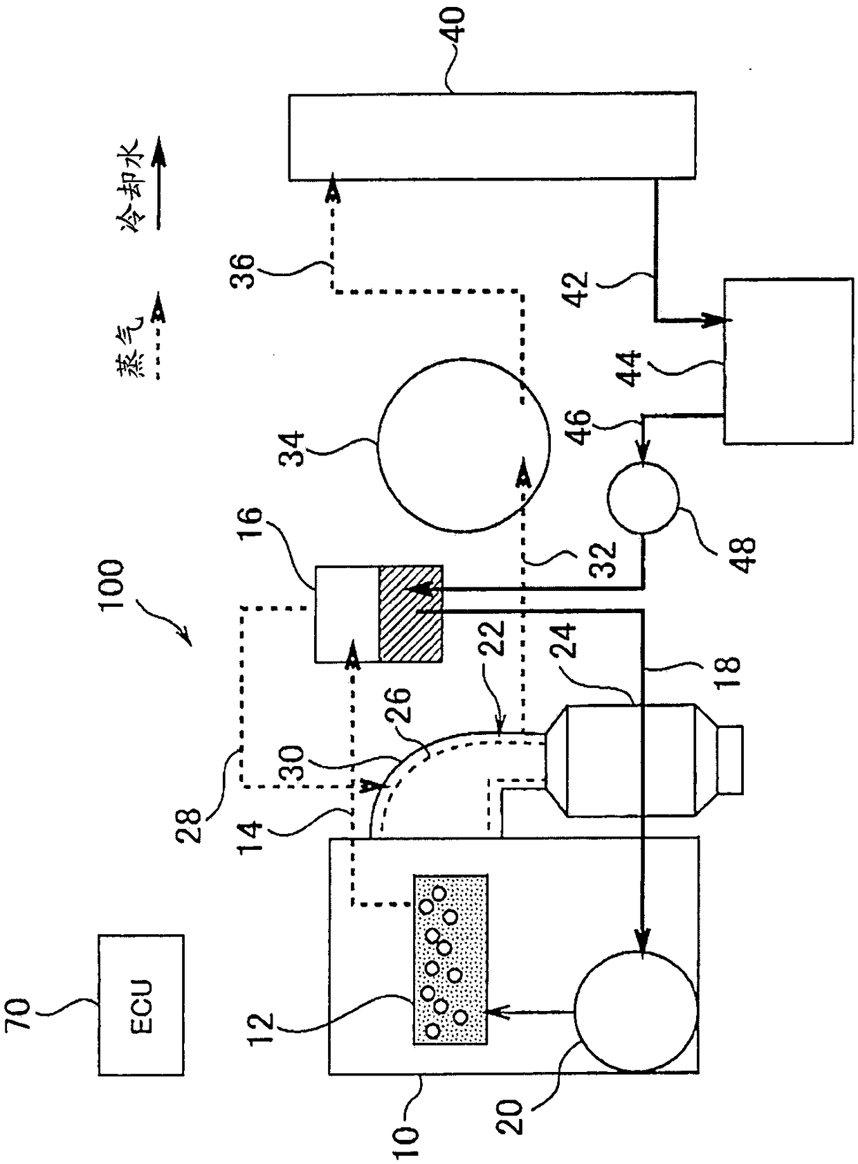
[0077] figure 1 It is a diagram showing the configuration of the Rankine cycle system 100 according to the first embodiment. The Rankine cycle system 100 of Embodiment 1 is configured as a Rankine cycle system for a vehicle that includes an internal combustion engine (engine) 10 and is mounted on a vehicle. The type and structure of the engine 10 are not limited. However, in the cylinder block and the cylinder head of the engine 10, a refrigerant passage 12 through which the refrigerant circulating in the engine 10 flows is formed. The refrigerant flow path 12 includes a water jacket surrounding the cylinder. Engine 10 is cooled by exchanging heat with the refrigerant flowing in refrigerant passage 12 . In this embodiment, water is used as the refrigerant.

[0078] The engine 10 is cooled by using waste heat of the engine 10 to boil the refrigerant flowing through the refrigerant passage 12 to vaporize part of the refriger...

Embodiment approach 2

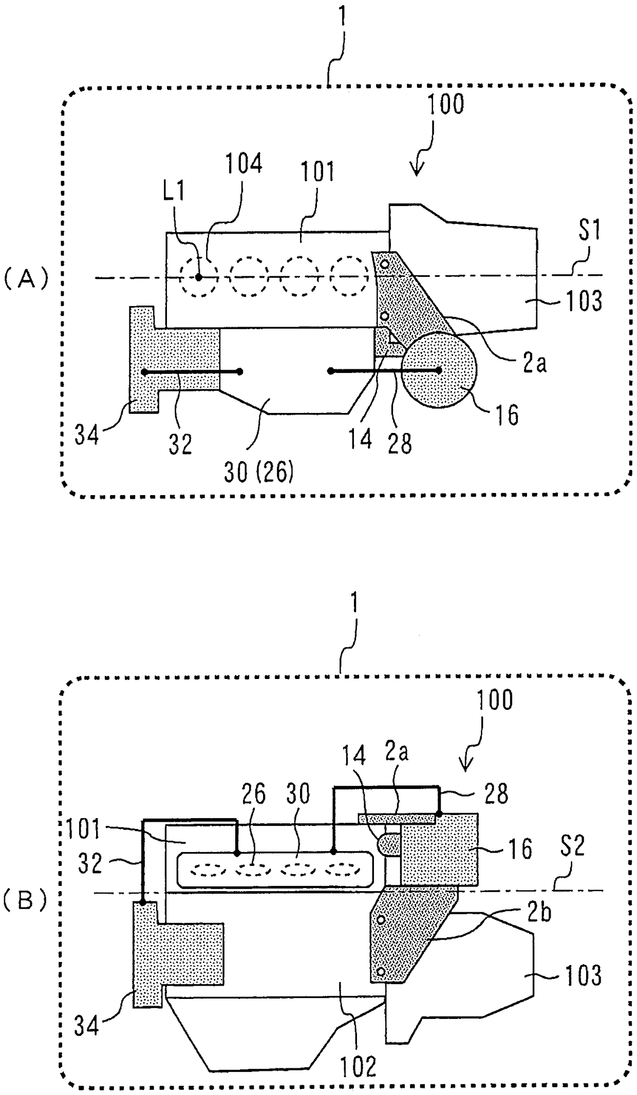
[0106] Next, the Rankine cycle system 110 according to Embodiment 2 will be described. Figure 7 It is a schematic diagram for explaining the fixed structure of the gas-liquid separator 16 in the Rankine cycle system 110 of Embodiment 2. In addition, (A) of the figure shows the top view of the vehicle of this Rankine cycle system, and (B) of the figure shows the front view of the vehicle of the Rankine cycle system mounted on a vehicle. Moreover, in Figure 7 in, for with figure 2 Common components of the Rankine cycle system 100 according to Embodiment 1 shown are denoted by the same reference numerals.

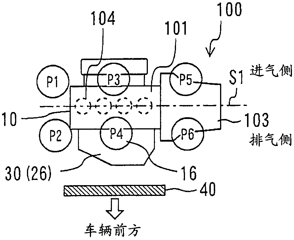
[0107] In the Rankine cycle system 110 according to Embodiment 2, the gas-liquid separator 16 is arranged in a region above the exhaust side of the engine 10 and at a position overlapping the superheater 30 or the exhaust manifold 26 in a plan view of the vehicle. The gas-liquid separator 16 is fixed to the engine 10 via the brackets 4a, 4b. The brackets 4a, 4b are resp...

Embodiment approach 3

[0111] Next, the Rankine cycle system 120 according to Embodiment 3 will be described. The Rankine cycle system 120 according to the third embodiment is characterized in that the cylinder head 101 and the gas-liquid separator 160 are integrally formed. Figure 8 and Figure 9 It is a schematic diagram for explaining the fixed structure of the gas-liquid separator in the Rankine cycle system 120 of Embodiment 3. It should be noted, Figure 8 A diagram showing a state in which the gas-liquid separator 160 is integrated with the cylinder head 101 viewed from the exhaust side, Figure 9 A diagram showing a disassembled state of the gas-liquid separator 160 and the cylinder head 101 viewed from the intake side.

[0112] As shown in these figures, a refrigerant inlet port 161 is provided in the gas-liquid separator 160 . The inlet port 161 is used to guide the refrigerant led out from the refrigerant passage 12 of the engine 10 to the gas-liquid separator 160 . The inlet port 1...


PUM


Abstract

The present invention provides a Rankine cycle system for vehicles. In the Rankine cycle system for vehicles, heat reception to a gas-liquid separator is promoted to improve the heat recovery efficiency of the Rankine cycle system. The Rankine cycle system includes: a boiler that imparts waste heat to the refrigerant circulating in the internal combustion engine to vaporize the refrigerant; and a gas-liquid separator that separates the gas-liquid two-phase refrigerant sent from the boiler into a gas-phase fluid and liquid phase fluid; a superheater, which superheats the gas phase fluid sent from the gas-liquid separator by exchanging heat with the exhaust gas of the internal combustion engine; an expander, which expands the gas phase fluid passing through the superheater to recover heat energy; and condensation A device that condenses the gas phase fluid passing through the expander back into a liquid phase fluid. The gas-liquid separator is fixed to the cylinder head of the internal combustion engine. Preferably, the gas-liquid separator includes a bracket, and is fixed to the cylinder head via the bracket.

Description

technical field [0001] The present invention relates to a Rankine cycle system for a vehicle, and more particularly to a mounting structure for mounting the Rankine cycle system on a vehicle. Background technique [0002] Patent Document 1 discloses a technique related to a Rankine cycle system mounted on a vehicle. In this Rankine cycle system, waste heat from the engine boils the liquid-phase fluid to change into a gas-phase fluid, expands the gas-phase fluid to perform work, and condenses the expanded gas-phase fluid to return to a liquid-phase fluid. [0003] prior art literature [0004] patent documents [0005] Patent Document 1: Japanese Patent Laid-Open No. 2015-94271 [0006] Patent Document 2: Japanese Patent Laid-Open No. 2002-316530 [0007] Patent Document 3: Japanese Patent Laid-Open No. 2011-189824 [0008] The problem to be solved by the invention [0009] When the Rankine cycle system is mounted on a mobile body such as a vehicle as in the above-menti...

Claims


Application Information

Patent Timeline
Patent Type & Authority Patents(China)
IPC IPC(8): F02G5/00F02G5/02F01K25/08
CPCF01K25/08F02G5/00F02G5/02F02G2254/15F01K23/065F01K23/10Y02E20/30Y02T10/12F05D2220/62H02K7/1823
Inventor 立野学
Owner TOYOTA JIDOSHA KK
Why Eureka
Try Eureka