Ship LNG vaporization system supplying heat through river water

A technology for river water and ships, applied in the field of ship LNG vaporization system, can solve the problems of lower thermal efficiency, lower working efficiency of LNG vaporizer, heat loss, etc., and achieve the effect of high freezing point and excellent thermal conductivity

A technology for river water and ships, applied in the field of ship LNG vaporization system, can solve the problems of lower thermal efficiency, lower working efficiency of LNG vaporizer, heat loss, etc., and achieve the effect of high freezing point and excellent thermal conductivity

CN106907273APending Publication Date: 2017-06-30广西利维船舶制造有限公司

Image

  • Ship LNG vaporization system supplying heat through river water

Examples


Embodiment Construction

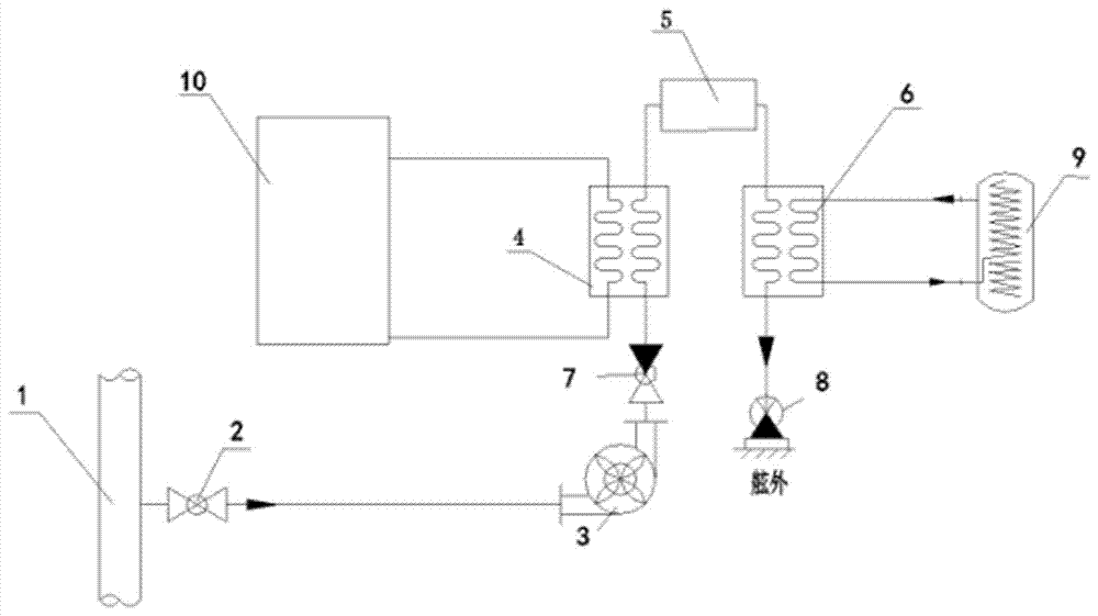
[0018] The ship LNG vaporization system using river water for heating includes a river water main pipe 1, a stop valve 2, an external cooling pump 3, an intercooler 4, a smoke exhaust water jacket 5, an ethylene glycol heat exchanger 6, and a stop check valve A7, stop check valve B8, LNG carburetor 9 and internal combustion engine 10, the river water main pipe 1 is connected with the external cooling pump 3 through the stop valve 2, and the external cooling pump 3 exchanges heat with the heat generated by the internal combustion engine 10 through the stop check valve A7 The intercooler 4 is connected, the intercooler 4 is connected with the water inlet end of the smoke exhaust water jacket 5, the water outlet end of the smoke exhaust water jacket 5 is connected with the ethylene glycol heat exchanger 6, and the ethylene glycol heat exchanger 6 is connected with the LNG vaporizer 9 , The drain of the glycol heat exchanger 6 is equipped with a stop check valve B8.

[0019] The s...


PUM


Abstract

A ship LNG vaporization system supplying heat through river water comprises a river water header pipe, a stop valve, an outer cooling pump, an intercooler, a smoke water draining sleeve, a glycol heat exchanger, a stop check valve, an LNG vaporizer and an internal combustion engine. According to the ship LNG vaporization system supplying the heat through the river water, the river water is extracted, excess heat produced by the internal combustion engine is absorbed by the intercooler to heat the river water, the river water is subjected to secondary heating through high-temperature tail gas exhausted by the internal combustion engine, thus, the river water can stably provide a heat source for the LNG vaporizer for a long term, and stable and efficient work of the LNG vaporizer is ensured.

Description

technical field [0001] The invention relates to the field of ship vaporizer structure, in particular to a ship LNG vaporization system using river water for heating. Background technique [0002] Modern river ships begin to use liquefied natural gas (LNG for short) as one of the fuels for internal combustion engines. The liquefied natural gas becomes liquid after being compressed and cooled to its boiling point (-161.5°C). Usually, the liquefied natural gas is stored in In the low-temperature storage tank at -161.5 degrees Celsius and about 0.1 MPa, the main component is methane, which is recognized as the cleanest fossil energy on earth. Colorless, odorless, non-toxic and non-corrosive, its volume is about 1 / 625 of the volume of the same volume of gaseous natural gas, and the mass of liquefied natural gas is only about 45% of the same volume of water. The manufacturing process is to first purify the natural gas produced in the gas field, and obtain it through a series of u...

Claims


Application Information

Patent Timeline
30 Jun 2017
Publication
CN106907273A
IPC
F02M21/06
CPC
F02M21/06; Y02T10/30
Inventors
廖森