A gas phase distribution device

A distribution device, gas phase technology, applied in fractionation, distillation regulation/control, etc., can solve the problems of difficult to control the gas distribution of the clapboard column, unable to achieve the optimal operating condition of the clapboard column, uneven distribution of the clapboard column, etc. Simple and effective, easy to install and change, simple to install

Inactive Publication Date: 2019-07-09
HEBEI UNIV OF TECH
View PDF3 Cites 2 Cited by
  • Summary
  • Abstract
  • Description
  • Claims
  • Application Information

AI Technical Summary

Problems solved by technology

[0008] In view of the fact that the gas distribution of the existing partition tower is difficult to control and the ratio of the gas flow rate automatically distributed on both sides of the partition often cannot reach the optimal operating condition of the partition tower, the technical problem to be solved by the present invention is to provide a gas distribution device, The device can automatically control the amount of gas entering both sides of the partition tower, which solves the problem of uneven distribution of gas entering the partition tower by self-control, and is convenient to use and maintain, and the pressure drop on both sides of the partition is small, which is more suitable for industrial applications

Method used


Image

  • A gas phase distribution device
  • A gas phase distribution device
  • A gas phase distribution device

Examples


Embodiment 1

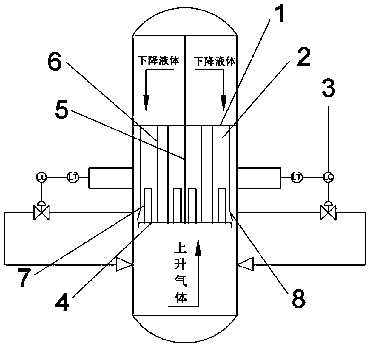
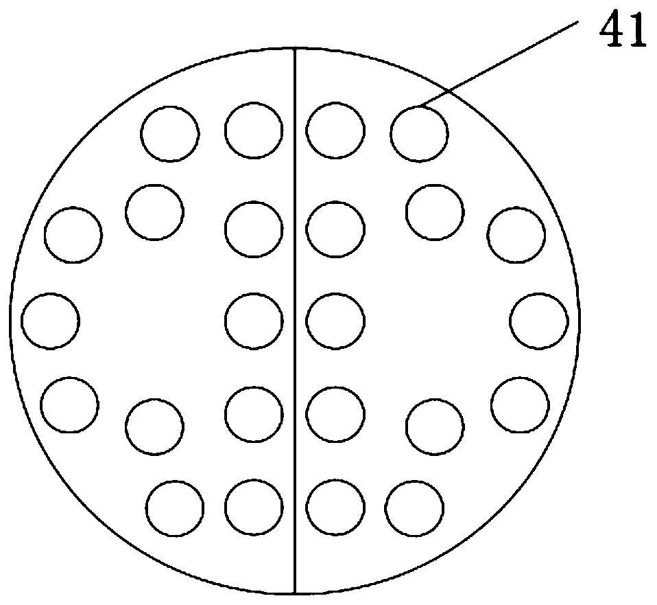
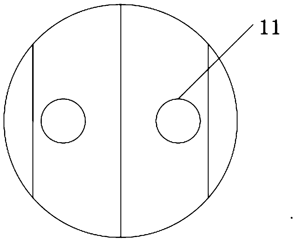
[0032] The gas phase distribution device of this embodiment is installed in a cold film partition tower with a diameter of 570mm. There are 24 openings for raising the gas on the gas-lifting pipe tray 4, each of which is a circular hole with a diameter of 50mm. The gas-lifting pipe on each gas-lifting hole is composed of a round pipe with a diameter of 50mm and a height of 300mm, and the gas-lifting pipe is welded at the corresponding opening; the diameter of the gas-lifting pipe is 100mm respectively welded on both sides of the partition, and the height of the gas-lifting pipe is the same as that of the gas-lifting pipe. The pressure drop regulating pipe 6 with the same height between the tray 4 and the pressure drop regulating plate 1, the lower part of the pressure drop regulating pipe 6 is closed and connected with the lift pipe tray 4, and the upper part is connected with the pressure drop regulating plate 1 through the pressure drop opening 11 The length of the long hole ...


PUM


Abstract

The invention relates to a gas phase distribution device. The device is characterized in that the device comprises a pressure drop regulating plate, a liquid level automatic control system, a gas riser pipe tower plate and pressure drop regulating pipes. The gas riser pipe tower plate is installed at the joint of a common stripping section and a main tower section. The edge of the gas riser pipe tower plate is seal-connected to the tower wall of a partition tower. The upper part of the gas riser pipe tower plate is divided into symmetrical left and right parts through a partition plate. The left and right parts are provided with the same number of gas riser holes in the same distribution way. A gas riser pipe is arranged at each one of the gas riser holes. The edge of the pressure drop regulating plate is seal-connected to the tower wall of the partition tower and is divided into symmetrical left and right parts through the partition plate. The left and right parts of the pressure drop regulating plate are provided with the same number of pressure drop holes in the same distribution way. Each one of the pressure drop holes is connected to the upper part of the pressure drop regulating pipe. The lower part of the pressure drop regulating pipe is seal-connected to the gas riser pipe tower plate in a vertical direction. Each one of the pressure drop regulating pipes is provided with a long hole.

Description

technical field [0001] The invention relates to the technical field of chemical separation, in particular to a gas phase distribution device. Background technique [0002] Distillation technology is one of the most mature and widely used separation technologies in contemporary chemical production. About 40% to 70% of the energy consumption in the chemical process is used for separation, and the rectification energy consumption accounts for 95% of it. In recent years, the continuous rise of energy prices has made the research on energy-saving technologies in the distillation process of great significance. Among them, the clapboard column, as a hot spot in the research of energy-saving technology, is being rapidly applied in industrial installations. The main feature of the partition tower is that there are one or more partitions in the tower, which divide the tower into several independent gas-liquid contact areas or spaces, and each area completes different separation task...

Claims


Application Information

Patent Timeline
Patent Type & Authority Patents(China)
IPC IPC(8): B01D3/14B01D3/32B01D3/42
CPCB01D3/14B01D3/32B01D3/42
Inventor 李春利姜挺马帅明闫磊
Owner HEBEI UNIV OF TECH
Why Eureka
Try Eureka