Utility tunnel

A technology of integrated pipe gallery and pipe gallery, which is applied in the direction of water conservancy projects, artificial islands, underwater structures, etc., can solve the problems of rainwater and sewage can not be used rationally, water waste, etc., to ensure maintenance safety and stability , high toughness and mechanical strength

Pending Publication Date: 2017-07-18
张铁耀
View PDF10 Cites 6 Cited by
  • Summary
  • Abstract
  • Description
  • Claims
  • Application Information

AI Technical Summary

Problems solved by technology

[0008] Although the urban comprehensive pipe gallery disclosed in this patent document can effectively drain away the rainwate

Method used


Image

  • Utility tunnel
  • Utility tunnel
  • Utility tunnel

Examples


Embodiment 1

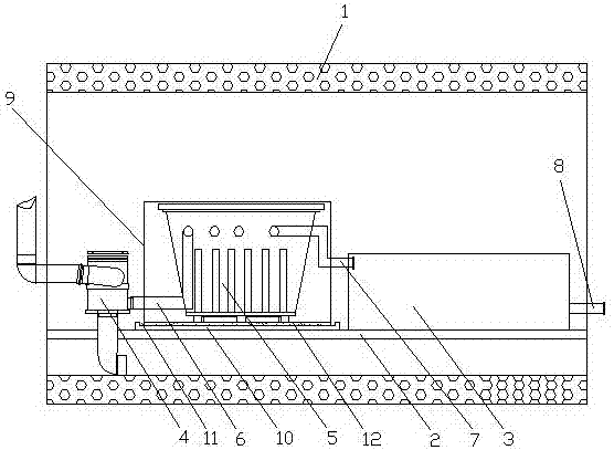
[0041] see figure 1 , a comprehensive pipe gallery, including a pipe gallery body 1, a partition 2 is arranged in the pipe gallery body 1, the lower surface of the partition 2 and the pipe gallery body 1 form a sewage discharge area, and a water treatment device is arranged on the partition 2 And water storage tank 3, described water treatment device comprises silt separator 4 and water treatment machine 5, and silt separator 4 is connected with water treatment machine 5 by first clean water pipe 6, and water treatment machine 5 is by second clean water pipe 7 Connected with the water storage tank 3, the water storage tank 3 is connected with the outlet pipe 8 passing through the main body of the pipe gallery 1, the main body of the pipe gallery 1 is also provided with a protection box 9, and the water treatment machine 5 is located in the protection box 9 , the partition board 2 is provided with a shockproof seat 10, the shockproof seat 10 is provided with a groove body 11, a...

Embodiment 2

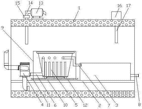
[0044] see figure 2 , a comprehensive pipe gallery, including a pipe gallery body 1, a partition 2 is arranged in the pipe gallery body 1, the lower surface of the partition 2 and the pipe gallery body 1 form a sewage discharge area, and a water treatment device is arranged on the partition 2 And water storage tank 3, described water treatment device comprises silt separator 4 and water treatment machine 5, and silt separator 4 is connected with water treatment machine 5 by first clean water pipe 6, and water treatment machine 5 is by second clean water pipe 7 Connected with the water storage tank 3, the water storage tank 3 is connected with the outlet pipe 8 passing through the main body of the pipe gallery 1, the main body of the pipe gallery 1 is also provided with a protection box 9, and the water treatment machine 5 is located in the protection box 9 , the partition board 2 is provided with a shockproof seat 10, the shockproof seat 10 is provided with a groove body 11, ...

Embodiment 3

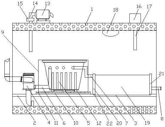
[0050] see image 3 , a comprehensive pipe gallery, including a pipe gallery body 1, a partition 2 is arranged in the pipe gallery body 1, the lower surface of the partition 2 and the pipe gallery body 1 form a sewage discharge area, and a water treatment device is arranged on the partition 2 And water storage tank 3, described water treatment device comprises silt separator 4 and water treatment machine 5, and silt separator 4 is connected with water treatment machine 5 by first clean water pipe 6, and water treatment machine 5 is by second clean water pipe 7 Connected with the water storage tank 3, the water storage tank 3 is connected with the outlet pipe 8 passing through the main body of the pipe gallery 1, the main body of the pipe gallery 1 is also provided with a protection box 9, and the water treatment machine 5 is located in the protection box 9 , the partition board 2 is provided with a shockproof seat 10, the shockproof seat 10 is provided with a groove body 11, a...


PUM


Abstract

The invention discloses a utility tunnel, and belongs to the field of municipal infrastructure construction. The utility tunnel comprises a tunnel body which is internally provided with a partition plate, and the lower surface of the partition plate and the tunnel body form a sewage disposal area. The utility tunnel is characterized in that the partition plate is provided with a water treatment device and a water storage box; the water treatment device comprises a silt separator and a water treatment machine; the silt separator is connected with the water treatment machine through a first clear water pipe; the water treatment machine is connected with the water storage box through a second clear water pipe; a water outlet pipe penetrating out of the tunnel body is connected to the water storage box; the tunnel body is further internally provided with a protection box; the water treatment machine is located in the protection box; a shockproof base is arranged on the partition plate and provided with a groove body; a foam plate is embedded in the groove body; and the protection box is fixed to the foam plate. According to the utility tunnel, the inner space of the tunnel body is reasonably utilized, all the components are reasonably laid out, the water treatment machine is stable in operation and good in shockproof performance, and good converting of sewage and rainwater can be effectively ensured.

Description

technical field [0001] The invention relates to the field of municipal infrastructure construction, in particular to a comprehensive pipe gallery. Background technique [0002] The comprehensive pipe corridor is the comprehensive corridor of underground urban pipelines. That is to build a tunnel space underground in the city, integrating various engineering pipelines such as power, communication, gas, heating, water supply and drainage, etc., with special inspection ports, hoisting ports and monitoring systems, implementing unified planning, unified design, Unified construction and management. [0003] The underground comprehensive pipe gallery system not only solves the problem of urban traffic congestion, but also greatly facilitates the maintenance and repair of municipal facilities such as electricity, communications, gas, water supply and drainage. [0004] The underground comprehensive utility corridor plays an important role in meeting the basic needs of people's li...

Claims


Application Information

Patent Timeline
IPC IPC(8): E02D29/045
CPCE02D29/045E02D29/10
Inventor 张铁耀赵天润樊军
Owner 张铁耀
Why Eureka
Try Eureka