Fabricated connecting structure used for suspension type monorail traffic track beam and construction method

A monorail transportation and connection structure technology, applied in the field of rail transportation, can solve the problems of complex support structure design, low construction and installation efficiency, difficult installation and adjustment, etc. Effect of installation error and prevention of left and right shaking

Active Publication Date: 2017-08-11
CHINA MCC5 GROUP CORP
View PDF11 Cites 18 Cited by
  • Summary
  • Abstract
  • Description
  • Claims
  • Application Information

AI Technical Summary

Problems solved by technology

[0003] Suspended track beams usually have two cross-section forms: I-shaped and bottom-opened box-shaped. When the cross-section is box-shaped with bottom open, the web of the track beam sometimes contacts with the guide wheels on the side, especially in curved roads. At this time, due to the effect of centrifugal force, the contact between the guide wheel and the web is more closely, which requires that the strength of the joint between two adjacent track beam webs is high enough and the flatness is good enough to ensure that the guide wheel passes through the joint smoothly and prevents the trolley from If the lower flange o...

Method used


Image

  • Fabricated connecting structure used for suspension type monorail traffic track beam and construction method
  • Fabricated connecting structure used for suspension type monorail traffic track beam and construction method
  • Fabricated connecting structure used for suspension type monorail traffic track beam and construction method

Examples


Embodiment Construction

[0028] The present invention will be further described below in conjunction with the accompanying drawings.

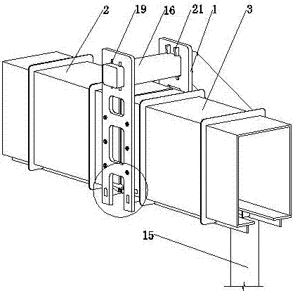
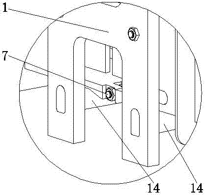
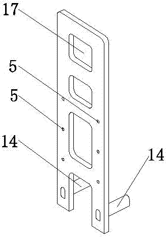
[0029] Such as Figures 1 to 9 As shown, the assembled connection structure for suspended monorail traffic track beams includes a bottom connection mechanism, a side connection mechanism and a support mechanism. The bottom connection mechanism realizes the stable and flat connection of the bottoms of the adjacent front and rear track beams 2 and 3 , the side connection mechanism realizes the stable and flat connection of the sides of the adjacent front and rear track beams 2 and 3, and the support mechanism realizes the overall stable support of the connected front and rear track beams 2 and 3 in the air at a certain distance from the ground, The side connection mechanism includes two side connection plates 1 symmetrically arranged on the left and right sides. After the cross-sections of the connecting ends of the adjacent front and rear track beams 2 and 3 are aligned...


PUM

PropertyMeasurementUnit
Lengthaaaaaaaaaa

Abstract

The invention relates to the technical field of track traffic, and discloses a fabricated connecting structure used for a suspension type monorail traffic track beam and a construction method. The fabricated connecting structure specifically comprises a bottom connecting mechanism, a side connecting mechanism and a supporting mechanism. The side connecting mechanism comprises side connecting plates which are arranged in a left-right symmetry mode. After sections of connecting ends of a front track beam and a rear track beam adjacent to the front track beam are aligned, the side connecting plates are attached to and mounted on the connecting position of webs on the two sides, the webs at the connecting ends of the front and rear track beams are provided with web mounting holes, the side connecting plates are provided with side connecting plate mounting holes corresponding to the web mounting holes, the side connecting plates and the corresponding webs can be connected through bolts, the inner surfaces of the positions, at the connecting end of the front track beam, of the webs and the inner surfaces of the positions, at the connecting end of the rear track beam, of the webs are located in the same plane, and flat connection of the side portions of the front and rear track beams is achieved. The fabricated connecting structure is simple in structure and fast and convenient to mount, the structural strength and flatness of the connecting position of the adjacent track beams are guaranteed, and comfort and safety of rail transport are improved.

Description

technical field [0001] The invention relates to the technical field of rail transit, in particular to an assembled connection structure and a construction method for a suspended monorail rail beam. Background technique [0002] The suspended monorail transportation system is the sky rail train. The track is above the train and supported in the air by steel or cement columns. Since the ground traffic is moved to the air, urban traffic problems can be alleviated without expanding the city's existing road facilities. And because it only moves the track into the air, instead of lifting the entire road into the air like elevated light rail or riding monorail, it overcomes the disadvantages of other rail transit systems and has many outstanding features and advantages in terms of construction and operation. . [0003] Suspended track beams usually have two cross-section forms: I-shaped and bottom-opened box-shaped. When the cross-section is box-shaped with bottom open, the web o...

Claims


Application Information

Patent Timeline
IPC IPC(8): E01B25/24E01B25/10
CPCE01B25/10E01B25/24
Inventor 周元王义唐丽王永景姜友荣廖兴国刘北贤陈艳
Owner CHINA MCC5 GROUP CORP
Why Eureka
Try Eureka